
Anti-collision transformer with high safety

A transformer and safety technology, applied in the field of anti-collision transformers, can solve the problems of poor anti-collision effect and inconvenient movement of transformers, and achieve the effect of solving the poor anti-collision effect.

Inactive Publication Date: 2020-11-13
宋允华
View PDF0 Cites 5 Cited by
  • Summary
  • Abstract
  • Description
  • Claims
  • Application Information

AI Technical Summary

Problems solved by technology

[0003] The existing transformer has poor anti-collision effect and is inconvenient to move

Method used


Image

  • Anti-collision transformer with high safety
  • Anti-collision transformer with high safety
  • Anti-collision transformer with high safety

Examples


Embodiment 1

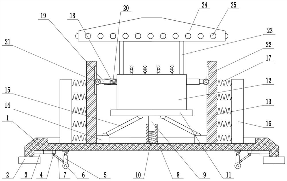
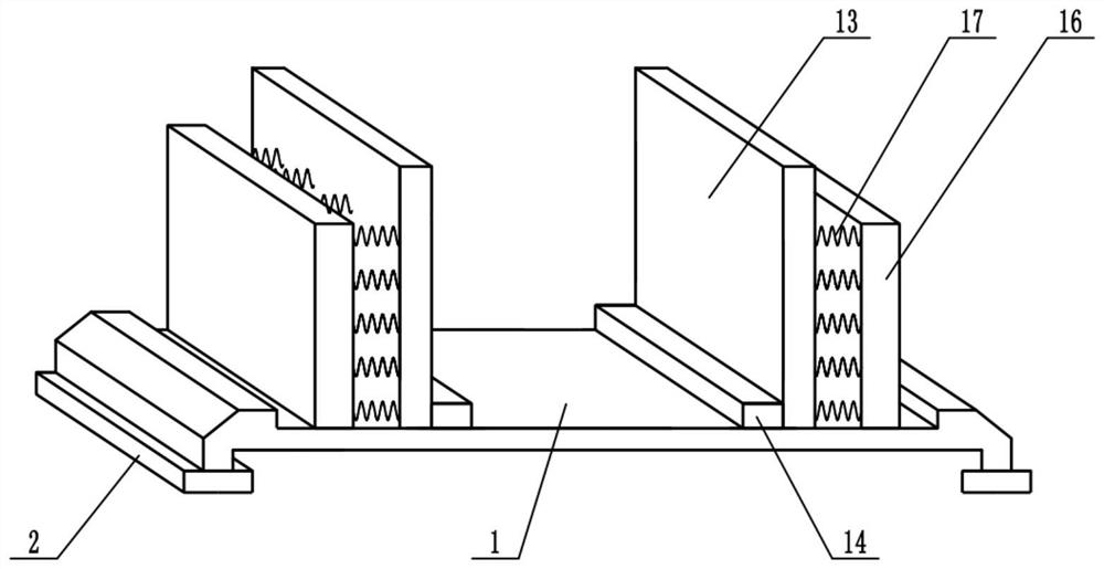
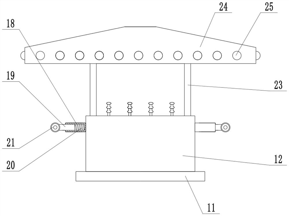
[0022] see Figure 1-3 , in an embodiment of the present invention, a high-safety anti-collision transformer includes a base 1, a foot 2, a mounting plate 11 and a transformer body 12, the two ends of the base 1 are respectively fixedly connected with the feet 2, and the base 1 The middle part of the upper surface is fixedly connected with the first sleeve 8, the first guide rod 9 is installed inside the first sleeve 8, the first guide rod 9 is slidingly connected with the first sleeve 8, the first guide rod 9 can slide up and down, The inside of the first sleeve 8 is equipped with a shock absorbing spring 10, the upper end of the first guide rod 9 is fixedly connected with a mounting plate 11, and the upper surface of the mounting plate 11 is fixedly connected with a transformer body 12, and the shock absorbing spring 10 can be used to reduce the vibration. The left and right sides of the mounting plate 11 are respectively provided with a movable plate 13, the movable plate 1...

Embodiment 2

[0024] On the basis of Embodiment 1, a moving mechanism is installed on the bottom of the base 1, and the moving mechanism includes a telescopic mechanism 3, a slider 4, a movable rod 5, a universal wheel 6 and a pull rod 7, and the bottom of the base 1 is fixedly connected with a telescopic Mechanism 3, the telescopic mechanism 3 is an electro-hydraulic telescopic cylinder, the extended end of the telescopic mechanism 3 is fixedly connected with a slider 4, and the slider 4 is slidably connected with the bottom of the base 1, and the telescopic mechanism 3 is controlled to expand and contract, which can drive the slider 4 around Sliding, the lower surface of the base 1 is hinged with a movable rod 5, the lower end of the movable rod 5 is equipped with a universal wheel 6, the lower surface of the slider 4 is hinged with a pull rod 7, the lower end of the pull rod 7 is hinged with the middle part of the movable rod 5, and the control The telescopic mechanism 3 stretches, drives...


PUM


Abstract

The invention relates to the field of power equipment. More particularly, the invention relates to an anti-collision transformer with high safety. The transformer comprises a base, supporting legs, amounting plate and a transformer body, wherein the supporting legs are fixedly connected to the two ends of the base correspondingly, a first sleeve is fixedly connected to the middle of the upper surface of the base, a first guide rod is mounted in the first sleeve, the upper end of the first guide rod is fixedly connected with the mounting plate, the upper surface of the mounting plate is fixedly connected with the transformer body, movable plates are respectively arranged on the left and right sides of the mounting plate, the side wall of the movable plate is fixedly connected with a mounting block, connecting rods are hinged to the upper surfaces of the mounting blocks, a buffer plate is further mounted on the upper surface of the base, guiding mechanisms are installed on the left sideand the right side of the transformer body respectively, and a buffering effect can be achieved through a buffering plate and a buffering spring. Meanwhile, under the effect of impact force, the movable plates move towards the inner side, the height of the transformer body is increased, kinetic energy is converted into gravitational potential energy, impact energy is further consumed, and thus the transformer body is protected.

Description

technical field [0001] The invention relates to the field of power equipment, more specifically, a high-safety anti-collision transformer. Background technique [0002] Transformer is a device that uses the principle of electromagnetic induction to change AC voltage. The main components are primary coil, secondary coil and iron core. The main functions are: voltage conversion, current conversion, impedance conversion, isolation, voltage stabilization (magnetic saturation transformer), etc. It is an indispensable power equipment in the power system. [0003] The existing transformer has poor anti-collision effect and is inconvenient to move. Contents of the invention [0004] The purpose of the present invention is to provide a high-safety anti-collision transformer to solve the problems raised in the above-mentioned background technology. [0005] To achieve the above object, the present invention provides the following technical solutions: [0006] A high-safety anti-...

Claims


Application Information

Patent Timeline
Patent Type & Authority Applications(China)
IPC IPC(8): H01F27/00H01F27/02H01F27/06
CPCH01F27/002H01F27/022H01F27/06
Inventor 宋允华
Owner 宋允华
Learn More