
Winding system and winding process method of inductance coil

A technology of inductance coil and winding, applied in the direction of inductance/transformer/magnet manufacturing, circuits, electrical components, etc., can solve problems such as affecting heat dissipation, copper wire failure, short circuit, etc.

Inactive Publication Date: 2020-11-13
陆林娣
View PDF0 Cites 4 Cited by
  • Summary
  • Abstract
  • Description
  • Claims
  • Application Information

AI Technical Summary

Problems solved by technology

[0003] In order to enhance the heat dissipation of high-frequency and high-current inductors, a predetermined gap should be formed between two adjacent coils, and they should not be close together. The existing flexible wire molds are all polished rods. Although they are wound according to a predetermined helical pitch during the winding process Yes, but in the actual operation process, it is still possible that the uneven internal stress may cause two turns of copper wires to be close together. If the two turns of copper wires are close to each other, if the enameled wire at the close position is damaged, a short circuit will occur. , so that a coil of copper wires fails, and close proximity also affects heat dissipation, so it is necessary to strictly control the helical pitch between two adjacent coils of copper wires in the process of winding the coil

Method used


Image

  • Winding system and winding process method of inductance coil
  • Winding system and winding process method of inductance coil
  • Winding system and winding process method of inductance coil

Examples


Embodiment Construction

[0037] The present invention will be further described below in conjunction with the accompanying drawings.

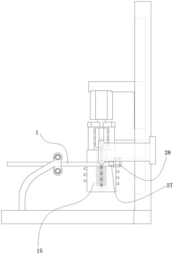
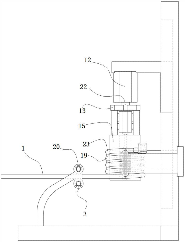
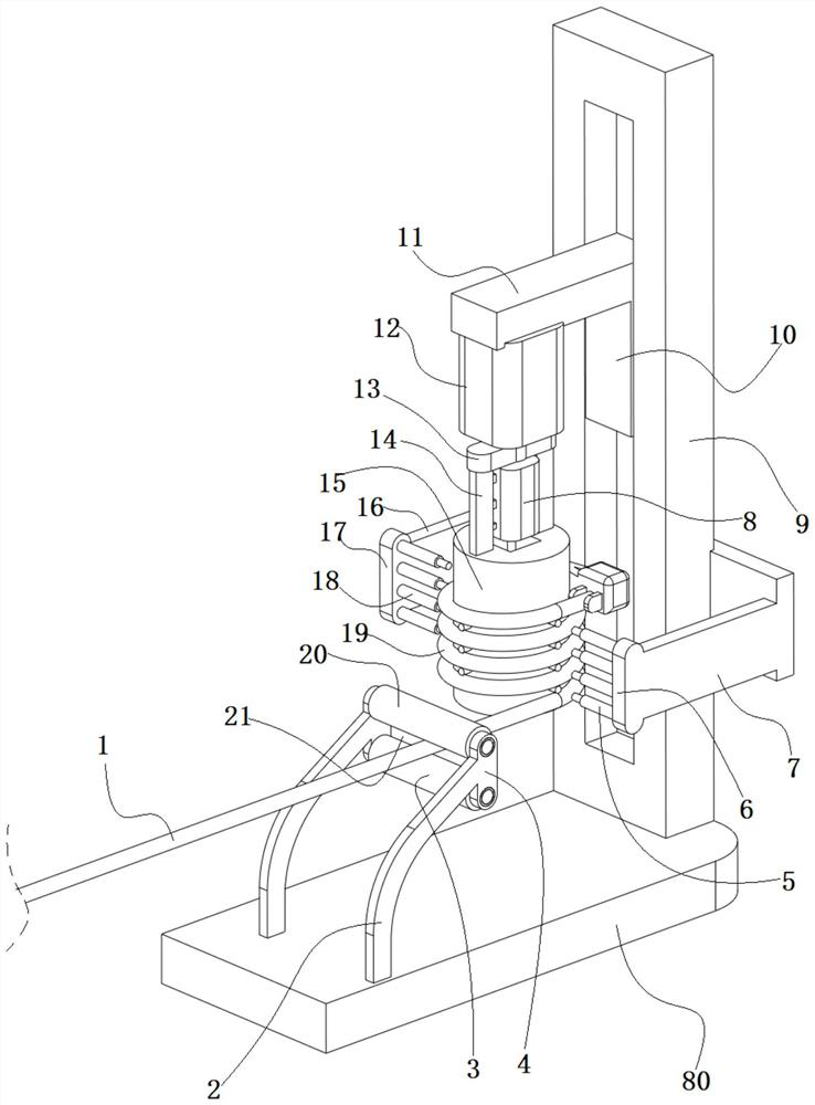
[0038] as attached Figures 1 to 10 The winding system of the inductance coil shown includes a horizontal base 2, a vertical lifting guide rail 9 is fixed on the horizontal base 80, and a lifting slider 10 capable of moving up and down is installed on the lifting guide rail 9. On the lifting slider 10, A cantilever beam 11 is fixedly connected, and a vertical first stepping motor 12 is fixedly installed on the lower side of the end of the cantilever beam 11, and a horizontal rotating beam 13 is fixedly connected to the lower end of the first output shaft 22 of the first stepping motor 12. The lower sides of both ends of the beam 13 are fixedly connected with the bobbins 15 through two vertical connecting arms 14;

[0039] The axis of the bobbin 15 is coaxial with the first output shaft 22 of the first stepping motor 12; the vertical displacement of the lifting slider ...


PUM


Abstract

The invention discloses a winding system of an inductance coil. The system comprises a horizontal base, a vertical lifting guide rail is fixed on the horizontal base; a lifting slide block capable ofmoving up and down is mounted on the lifting guide rail; a cantilever beam is fixedly connected to the lifting sliding block, a vertical first stepping motor is fixedly installed in the lower side ofthe tail end of the cantilever beam, a horizontal rotating cross beam is fixedly connected to the lower end of a first output shaft of the first stepping motor, and winding reels are fixedly connectedto the lower sides of the two ends of the rotating cross beam through two vertical connecting arms. The space between every two adjacent circles of a spiral inductance coil product is rigidly restrained by a coil spiral distance restraining pile, so that the distance between any two circles of the spiral inductance coil product is strictly restrained by the coil spiral distance restraining pile,and then the situation that two circles of copper wires are close to each other in the winding process of the spiral inductance coil product due to uneven internal stress in the copper wires in the winding process is avoided.

Description

technical field [0001] The invention belongs to the field of inductor manufacturing. Background technique [0002] High-frequency and high-current inductors need to use air-core inductors. Air-core inductors have only coils and no magnetic cores. They need to be wound on the winding mold before removing the mold; [0003] In order to enhance the heat dissipation of high-frequency and high-current inductors, a predetermined gap should be formed between two adjacent coils, and they should not be close together. The existing flexible wire molds are all polished rods. Although they are wound according to a predetermined helical pitch during the winding process Yes, but in the actual operation process, it is still possible that the uneven internal stress may cause two turns of copper wires to be close together. If the two turns of copper wires are close to each other, if the enameled wire at the close position is damaged, a short circuit will occur. , so that a coil of copper wi...

Claims


Application Information

Patent Timeline
Patent Type & Authority Applications(China)
IPC IPC(8): H01F41/066H01F41/098
CPCH01F41/066H01F41/098
Inventor 陆林娣
Owner 陆林娣
Learn More