
Fuel distributor for internal combustion engines

一种燃料分配器、燃料分配的技术,应用在低压燃料喷射、低压燃料喷射、燃料喷射装置等方向,能够解决受限应用领域、费事制造插入件等问题,达到改善减振特性、实现成本、改善构型和工作方式的效果

Active Publication Date: 2020-11-13
ROBERT BOSCH GMBH
View PDF7 Cites 0 Cited by
  • Summary
  • Abstract
  • Description
  • Claims
  • Application Information

AI Technical Summary

Problems solved by technology

[0003] The fuel distributor strip known from DE 10 2014 205 179 A1 has the disadvantage that the insert must be produced in a complex manner, since it is designed as a thick-walled tube with grooves
Furthermore, the known fuel distributor strips restrict the radial supply of fuel, resulting in a restricted field of application

Method used


Image

  • Fuel distributor for internal combustion engines
  • Fuel distributor for internal combustion engines
  • Fuel distributor for internal combustion engines

Examples


Embodiment Construction

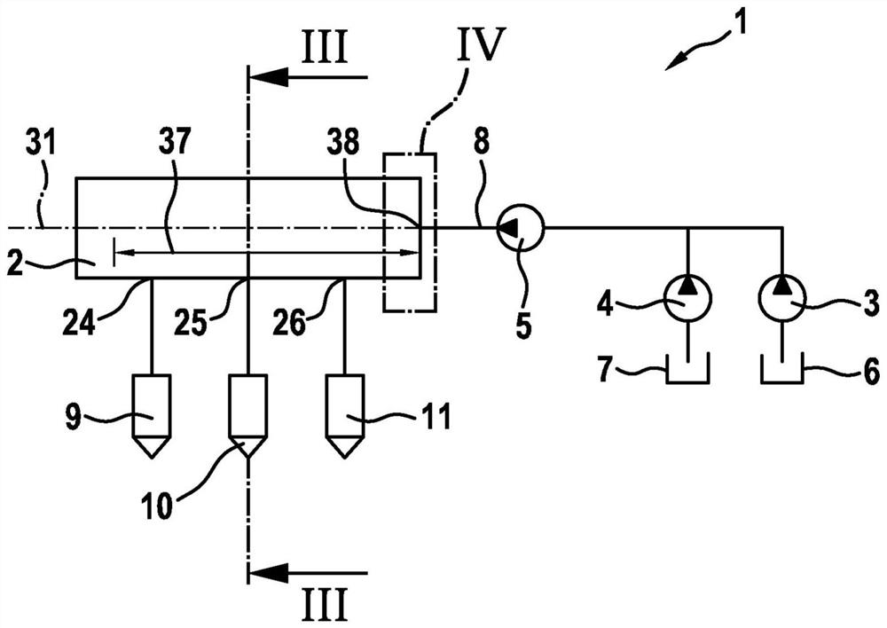
[0019] figure 1 A schematic diagram of a fuel injection system 1 with a fuel distributor 2 according to the first exemplary embodiment is shown. In this exemplary embodiment, the fuel injection system 1 has a fuel pump 3 and a metering unit 4 designed as a backing pump 4 . Furthermore, a high-pressure pump 5 is provided. A fuel pump 3 delivers liquid fuel from a tank 6 to a high pressure pump 5 . The dosing unit 4 is used for sometimes dosing water from the storage container 7 into the delivered fuel. In this exemplary embodiment, the metering takes place upstream of the high-pressure pump 5 . In a variant embodiment, the metering can also take place at the high-pressure pump 5 . Depending on the operating state, liquid fuel or a mixture of liquid fuel and water is then conveyed in line section 8 arranged between fuel distributor 2 and high-pressure pump 4 . Depending on the configuration, the water content in the mixture can be predetermined fixedly or can also vary over...


PUM


Abstract

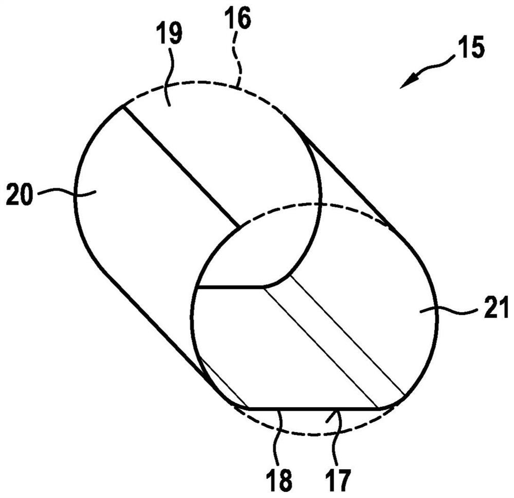
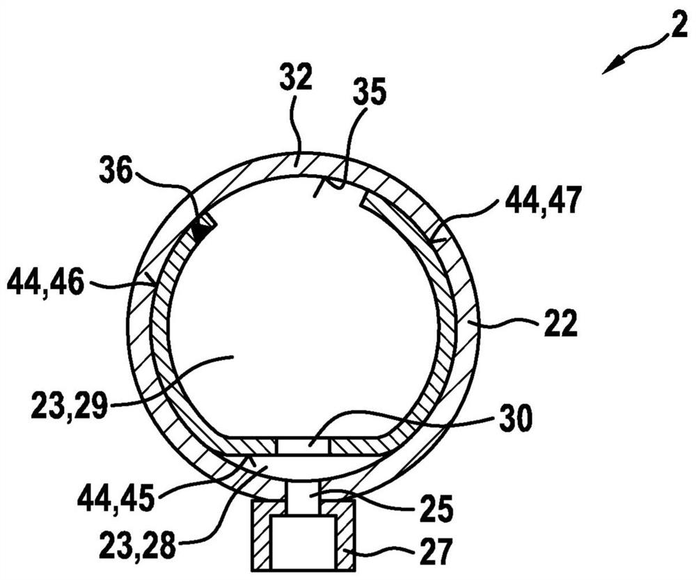
A fuel distributor (2), which serves in particular as a fuel distributor rail for mixture-compressing, applied-ignition internal combustion engines, comprises a main body (22), on which at least one high-pressure inlet (38) and multiple high-pressure outlets (24 - 26) are provided. Also provided is an insert body (15) which is arranged in an interior space (23) of the main body (22). Of the interior space (23), the insert body (15) at least substantially separates an inflow region (28), which extends from the high-pressure inlet (38) to the high-pressure outlets (24-26), from a clamping region(29). The insert body (15) is formed as a thin-walled insert body (15), which forms a partition (18) extending at least from the high-pressure inlet (38) to the high-pressure outlets (24-26) throughthe interior space (23).

Description

technical field [0001] The invention relates to a fuel distribution valve, in particular a fuel distribution bar for hybrid compression externally ignited internal combustion engines. In particular, the invention relates to the field of fuel injection systems for motor vehicles in which fuel is injected directly into the combustion chamber of an internal combustion engine. Background technique [0002] A fuel distribution rail for an internal combustion engine is known from DE 10 2014 205 179 A1. The known fuel distributor strip has an elongated housing with a cavity, a fuel inflow into the cavity and at least two fuel outflows from the cavity, each for one fuel injector. In this case, a body is arranged in the cavity, which has a groove connecting the two fuel outflows to one another and, in the region of the fuel inflow, has a groove radially surrounding the body. A body with two grooves serves as an insert, by means of which a direct flow of fuel from the pump into the ...

Claims


Application Information

Patent Timeline
Patent Type & Authority Applications(China)
IPC IPC(8): F02M55/02F02M55/04F02M69/46
CPCF02M55/025F02M55/04F02M69/465F02M2200/315F02M63/0275
Inventor K·朱斯A·申克祖施魏因斯贝格M·阿姆勒M·鲍尔
Owner ROBERT BOSCH GMBH
Learn More