
Clamping device for machining of thin-wall part

A technology of clamping device and thin-walled parts, which is applied in the field of processing parts, can solve the problems of easy deformation, clamping force, parts falling, and insufficient

Inactive Publication Date: 2020-11-17
CHINA FIRST AUTOMOBILE
View PDF11 Cites 0 Cited by
  • Summary
  • Abstract
  • Description
  • Claims
  • Application Information

AI Technical Summary

Problems solved by technology

[0006] In order to overcome the above problems, the present invention provides a clamping device for processing thin-walled parts, which can solve the technical problems that the thin-walled parts of the revolving body are easily deformed during the clamping process and the parts fall due to insufficient clamping force.

Method used


Image

  • Clamping device for machining of thin-wall part
  • Clamping device for machining of thin-wall part
  • Clamping device for machining of thin-wall part

Examples


Embodiment Construction

[0027] The present invention will be further described in detail below in conjunction with the accompanying drawings and embodiments. It should be understood that the specific embodiments described here are only used to explain the present invention, but not to limit the present invention. In addition, it should be noted that, for the convenience of description, only some structures related to the present invention are shown in the drawings but not all structures.

[0028] In the description of the present invention, unless otherwise clearly specified and limited, the terms "connected", "connected" and "fixed" should be understood in a broad sense, for example, it can be a fixed connection, a detachable connection, or an integrated ; It can be a mechanical connection or an electrical connection; it can be a direct connection or an indirect connection through an intermediary, and it can be the internal communication of two components or the interaction relationship between two ...


PUM


Abstract

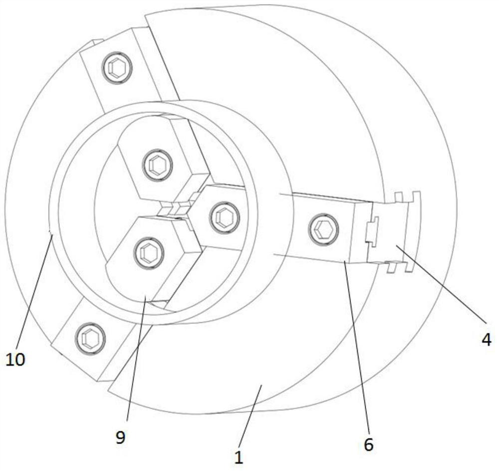
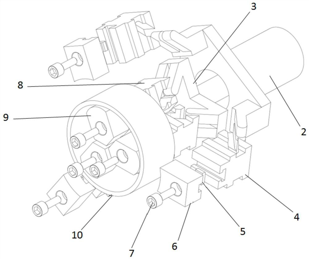
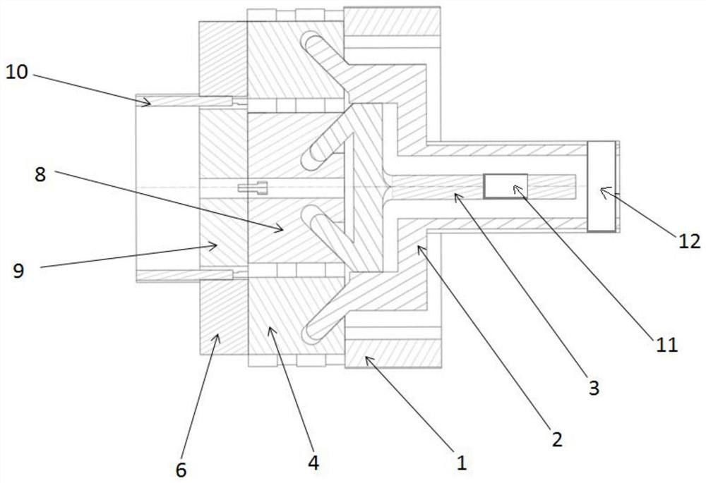
The invention belongs to the technical field of machined parts, and particularly relates to a clamping device for machining of a thin-wall part. Multiple inner claws are glidingly connected inside a main body; each inner claw can slide in the radial direction of the main body; the outside of the main body is glidingly connected with multiple outer claws corresponding to the inner claws; each outerclaw can slide in the radial direction of the main body; and the right end of an inner claw pulling rod is sleeved with an outer claw pulling rod; the right end of each inner claw is connected with one slope at the left end of the inner claw pulling rod in a matched manner, so that the inner claw can slide along the slope at the left end of the inner claw pulling rod; the right end of each outerclaw is connected with one slope at the left end of the outer claw pulling rod in a matched manner, so that the outer claw can slide along the slope at the left end of the outer claw pulling rod; andpressure sensors are arranged on the inner claw pulling rod and the outer claw pulling rod respectively. The technical problems that a revolving body thin-wall part is prone to deformation in the clamping process and the part falls off due to the insufficient clamping force can be solved.

Description

technical field [0001] The invention belongs to the technical field of processing parts, and in particular relates to a clamping device for processing thin-walled parts. Background technique [0002] Turning of thin-walled parts is often encountered in the processing of rotary parts. At present, there are three main clamping methods used for processing thin-walled parts: [0003] The first is to turn the chuck jaws into the shape of the desired clamping position, maximizing the contact area between the part and the jaws to reduce clamping deformation. The problem with this clamping method is: the turning chuck grip can reduce the problem of clamping deformation, but it cannot be completely avoided. And the jaws after turning are only suitable for the processing of one kind of parts. [0004] The second is to use a pressure plate to compress in the vertical direction of the thin wall, and the pressure does not directly act on the surface of the thin wall to reduce deformati...

Claims


Application Information

Patent Timeline
IPC IPC(8): B23B31/02B23Q3/06
CPCB23B31/02B23Q3/06
Inventor 周仁杰刘井泽王乐杨永修张兴野王健夫张瑜张人搏霍星宇仉天玺
Owner CHINA FIRST AUTOMOBILE
Learn More