A self-adaptive clip joint clamping device

A clamping device and connecting head technology, applied in flange connection, pipe/pipe joint/pipe fitting, passing element, etc., can solve problems such as poor sealing, loose connection of pipe joints, and reduced sealing performance of joints

Active Publication Date: 2021-07-13
SHANDONG QILONG OFFSHORE PETROLEUM STEEL PIPE
View PDF9 Cites 0 Cited by
  • Summary
  • Abstract
  • Description
  • Claims
  • Application Information

AI Technical Summary

Problems solved by technology

[0002] During oilfield exploitation, pipelines for transporting oil need to be dismantled and installed frequently to meet oil exploitation in different locations. The clamp joints are uniquely designed, novel and reasonable in structure, and reliable in performance, which brings great convenience and benefits to engineering construction and maintenance. Widely used in oil transportation pipelines. Although the existing clamp joints are simple in structure, the adaptability of the clamps is poor. One type of clamp can only be used for the corresponding type of joints, and oil transportation pipelines have different models. Therefore, The pipe joints used are also different. It is necessary to correspond the clamps to the pipe joints one by one, and some clamps are of the same size, which are difficult to distinguish and easy to confuse, resulting in too tight connection of the pipe joints, damage to the clamps, or improper connection of the pipe joints. Tight, poor sealing, which brings a lot of inconvenience to the selection of clamps. At the same time, the clamping force of the existing two-half clamps on the joints cannot be evenly distributed on the convex edges of the joints, so that the two joints are misplaced. Silicone pads The uneven extrusion of the sheet leads to a decrease in the sealing performance of the joint, or the clamp is easily deformed, resulting in a decrease in the sealing performance and cannot meet the actual needs. Therefore, we have invented a clamping device for the joint of the adaptive clamp

Method used


Image

  • A self-adaptive clip joint clamping device
  • A self-adaptive clip joint clamping device
  • A self-adaptive clip joint clamping device

Examples


Embodiment Construction

[0014] In order to make the purpose, technical solutions and advantages of the embodiments of the present invention clearer, the technical solutions in the embodiments of the present invention will be clearly and completely described below in conjunction with the drawings in the embodiments of the present invention. Obviously, the described embodiments It is a part of embodiments of the present invention, but not all embodiments. Based on the embodiments of the present invention, all other embodiments obtained by persons of ordinary skill in the art without creative efforts fall within the protection scope of the present invention.

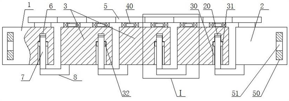
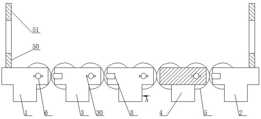
[0015] An adaptive clamp joint clamping device, such as figure 1 As shown, including the first T-shaped block 1 and the second T-shaped block 2, a row of several third T-shaped blocks 3 is arranged between the first T-shaped block 1 and the second T-shaped block 2, and the first T-shaped block 1. The second T-block 2 and the third T-block 3 are T...


PUM


Abstract

A clamping device for an adaptive clamp joint head, the invention belongs to the field of joint clamps, comprising a first T-shaped block and a second T-shaped block, one side of the first T-shaped block and the second T-shaped block are respectively fixed and installed For the same gear, the adjacent gears mesh with each other, and the other sides of the first T-shaped block and the third T-shaped block are respectively provided with pin holes, and the pin rods are movable and installed in the pin holes, and the outer ends of the pin rods are respectively connected to the corresponding The third T-shaped block or the second T-shaped block is fixedly connected by a connecting rod. The present invention has simple structure and ingenious concept. By dividing the clamp into several small units that can be flexibly assembled, the corresponding number of third T-shaped blocks can be selected according to the diameter of the joint to be clamped, so that the clamp can adapt to joints of different diameters. At the same time, when a small unit is damaged, the small unit can be replaced to avoid the waste caused by the replacement of the entire clamp, and the clamping force formed by each small unit on the joint is the same.

Description

technical field [0001] The invention belongs to the field of pipe joint clips, in particular to a clamping device for a self-adaptive clip connection head. Background technique [0002] During oilfield exploitation, pipelines for transporting oil need to be dismantled and installed frequently to meet oil exploitation in different locations. The clamp joints are uniquely designed, novel and reasonable in structure, and reliable in performance, which brings great convenience and benefits to engineering construction and maintenance. Widely used in oil transportation pipelines. Although the existing clamp joints are simple in structure, the adaptability of the clamps is poor. One type of clamp can only be used for the corresponding type of joints, and oil transportation pipelines have different models. Therefore, The pipe joints used are also different. It is necessary to correspond the clamps to the pipe joints one by one, and some clamps are of the same size, which are difficu...

Claims


Application Information

Patent Timeline
Patent Type & Authority Patents(China)
IPC IPC(8): F16L23/036F16L23/22
CPCF16L23/036F16L23/22
Inventor 王志明孟庆滨马会珍
Owner SHANDONG QILONG OFFSHORE PETROLEUM STEEL PIPE
Why Eureka
Try Eureka