Tool grinding equipment

A tool and equipment technology, applied in the field of tool grinding equipment, can solve the problem that the tool clamping force is not easy to control, and achieve the same effect of the clamping force

Active Publication Date: 2021-05-07
GUANGDONG UCAN ROBOT TECH CO LTD
View PDF12 Cites 0 Cited by
  • Summary
  • Abstract
  • Description
  • Claims
  • Application Information

AI Technical Summary

Problems solved by technology

[0003] In order to overcome the disadvantage that the tool clamping force in the prior art is not easy to control, the object of the present invention is to provide a tool grinding device, which can realize the purpose of uniform clamping force and improve the quality of tool grinding

Method used


Image

  • Tool grinding equipment
  • Tool grinding equipment
  • Tool grinding equipment

Examples


Embodiment Construction

[0060] In order to facilitate the understanding of those skilled in the art, the present invention will be further described below in conjunction with the embodiments and accompanying drawings, and the contents mentioned in the implementation modes are not intended to limit the present invention.

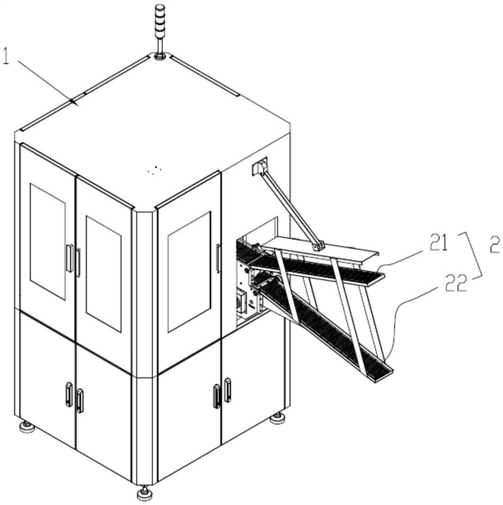
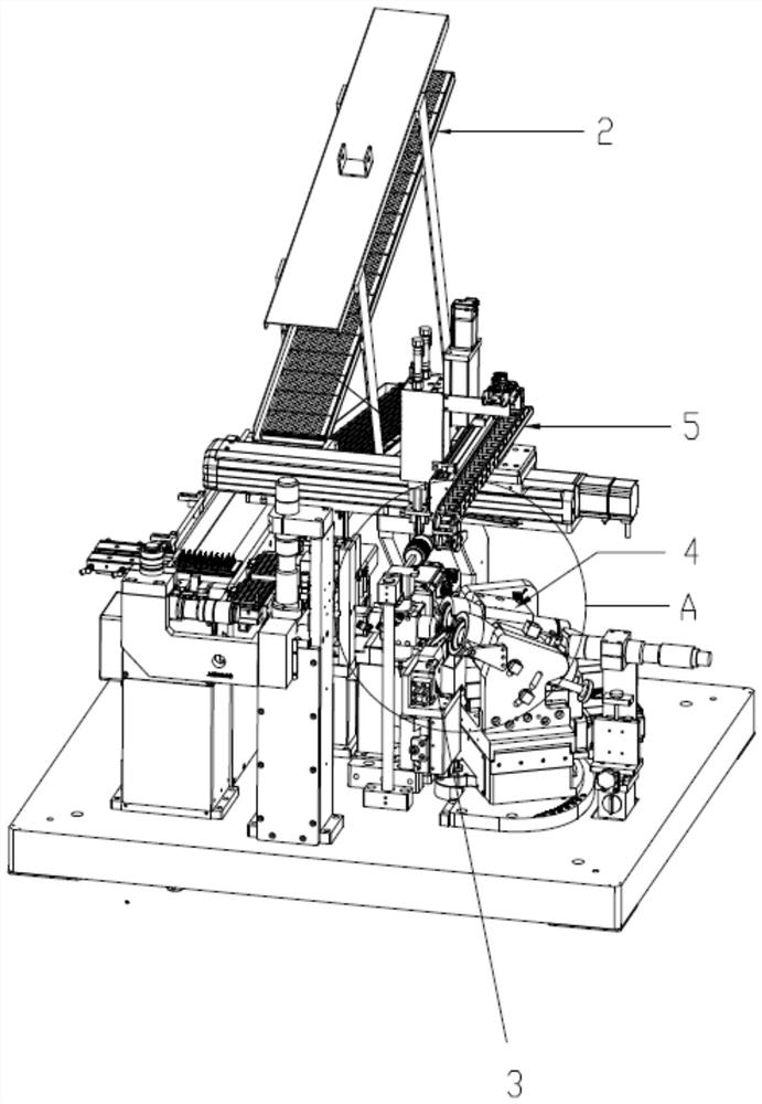
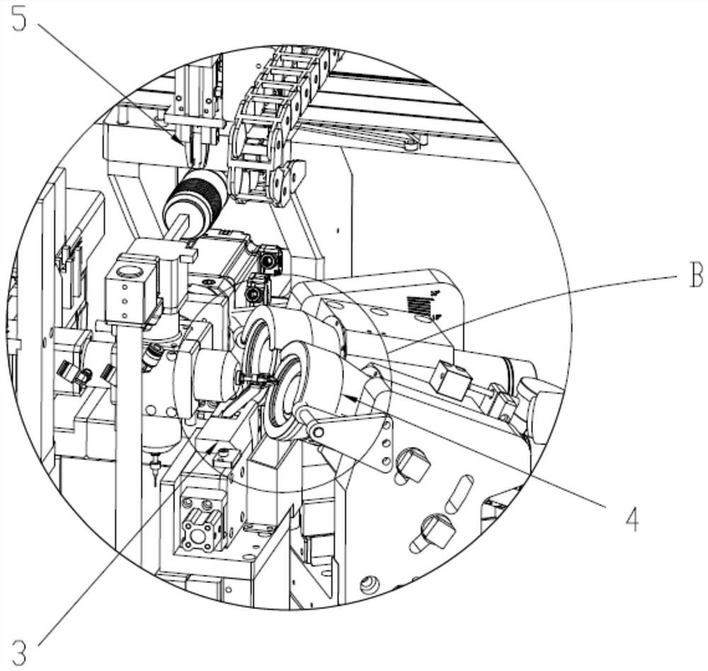
[0061] see Figure 1 to Figure 15 , a tool grinding device of the present invention, comprising a machine case 1, a tool conveying device 2, a tool holding device 3, a tool grinding wheel device 4 and a tool transfer device 5, the tool holding device 3 is arranged in the machine case 1 and holds The tool supplied by the tool conveying device 2, the tool grinding wheel device 4 is arranged in the cabinet 1 and grinds the tool clamped by the tool clamping device 3, and the tool transfer device 5 is arranged in the cabinet 1 and transports the tool The tool conveyed by the device 2 is transferred to the tool clamping device 3 or the tool ground by the tool grinding wheel device 4 is tr...


PUM


Abstract

The invention relates to the technical field of tool grinding, in particular to tool grinding equipment which comprises a case, a tool conveyor device, a tool clamping device, a tool grinding wheel device and a tool transfer device. The tool clamping device comprises a clamping assembly, and the clamping assembly comprises a mounting plate, a tool driving part, a left clamping part, a right clamping part and a shifting part; the left clamping part is rotatably connected with the mounting plate, the right clamping part is rotatably connected with the left clamping part, and the left clamping part and the right clamping part are matched for clamping a tool; the shifting part comprises a body, a first convex column and a second convex column, and the body is rotatably connected to the mounting plate; the tool driving part is arranged on the mounting plate, and used for driving the body to swing; the right clamping part is driven by the first convex column to swing, and the left clamping part is driven by the second convex column to swing; and the swing directions of the left clamping part and the right clamping part are opposite. Through arrangement of the shifting part, the shifting part is rotated to drive the first convex column and the second convex column to rotate synchronously, so that the left clamping part and the right clamping part are rotated synchronously and reversely, and the purpose that the clamping forces for clamping the tool are the same is achieved.

Description

technical field [0001] The invention relates to the technical field of tool grinding, in particular to a tool grinding device. Background technique [0002] When grinding the blade of a tool, it is necessary to clamp the tool handle of the tool. The existing grinding device has uneven clamping force when clamping the tool handle, especially when clamping a tool with a tool handle diameter smaller than φ3, the clamping The force is more difficult to control, which affects the efficiency and precision of tool grinding, and cannot meet the production requirements. Contents of the invention [0003] In order to overcome the disadvantage of difficult control of tool clamping force in the prior art, the object of the present invention is to provide a tool grinding device, which can realize the purpose of uniform clamping force and improve the quality of tool grinding. [0004] To achieve the above object, the technical solution of the present invention is: [0005] A kind of t...

Claims


Application Information

Patent Timeline
IPC IPC(8): B24B3/00B24B41/00B24B41/06B24B47/22
CPCB24B3/00B24B41/005B24B41/06B24B47/22
Inventor 王俊锋黄春雷王哲
Owner GUANGDONG UCAN ROBOT TECH CO LTD
Why Eureka
Try Eureka