
Double-shaft expandable mandrel

A core-expanding and rigid technology, applied in the field of double-axis expandable mandrels, can solve the problems of the negative influence of the outer circle accuracy of the workpiece, the uneven clamping deformation of the workpiece, and the unbalanced clamping force, so as to improve the clamping uniformity, The effect of reducing roundness error and improving accuracy

Pending Publication Date: 2021-03-16
史晶晶
View PDF9 Cites 0 Cited by
  • Summary
  • Abstract
  • Description
  • Claims
  • Application Information

AI Technical Summary

Problems solved by technology

[0003] Firstly, when the elastic mandrel moves to the left along the axial direction, the radial expansion of the spring piece increases from right to left, so that the actual radial clamping force obtained by the workpiece changes from right to left, and Gradually increasing, the clamping force of the workpiece at both ends of the axial direction is unbalanced, which has a negative impact on the accuracy of the outer circle of the workpiece
[0004] Secondly, as the radial dimension of the expandable mandrel expands, the contact between the outer surface of the mandrel spring and the inner hole of the workpiece is closer to point contact. Such radial clamping force is located on one side of the workpiece and is uniformly distributed along the circumferential direction. 3 lines, resulting in uneven clamping deformation of the workpiece, resulting in a large roundness error in the outer circle of the workpiece

Method used


Image

  • Double-shaft expandable mandrel
  • Double-shaft expandable mandrel
  • Double-shaft expandable mandrel

Examples


Embodiment Construction

[0019] The following will clearly and completely describe the technical solutions in the embodiments of the present invention with reference to the accompanying drawings in the embodiments of the present invention. Obviously, the described embodiments are only some, not all, embodiments of the present invention. Based on the embodiments of the present invention, all other embodiments obtained by persons of ordinary skill in the art without making creative efforts belong to the protection scope of the present invention.

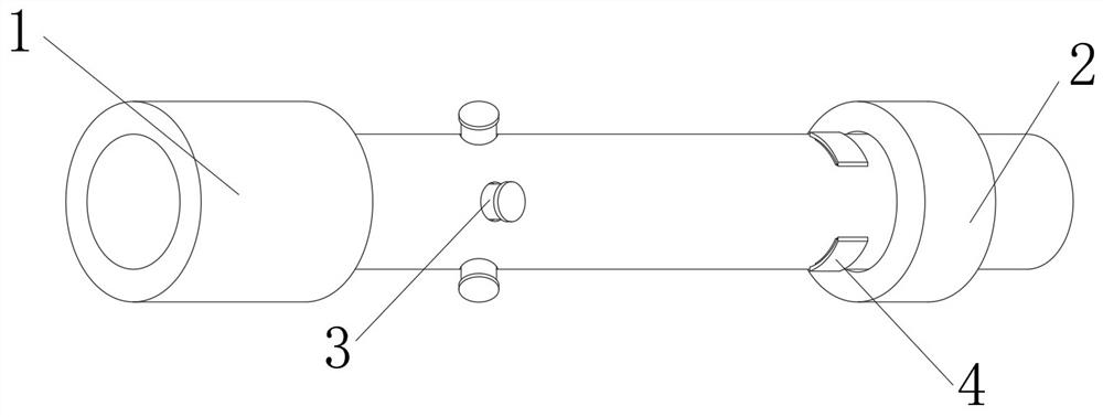
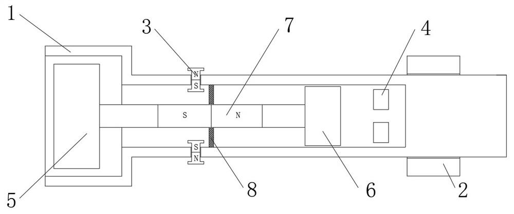
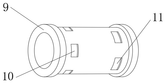
[0020] see Figure 1-4 , a double-axis expandable mandrel, including a rigid mandrel 1, one end of the rigid mandrel 1 is connected with a cylinder, and the end of the rigid mandrel 1 close to the cylinder is clamped on a rotating device so as to cut the outer circle of the workpiece, the rigid mandrel The other end of the shaft 1 is movably socketed with the limit bolt 2, and the workpiece is limited during the cutting process through the limit bolt 2. The ou...


PUM


Abstract

The invention relates to the technical field of clamp equipment, and discloses a double-shaft expandable mandrel. The double-shaft expandable mandrel comprises a rigid mandrel, wherein an air cylinderis connected to one end of the rigid mandrel; a limiting bolt is movably connected to the other end of the rigid mandrel in a sleeving mode; magnetic ejection pieces away from one end of the limitingbolt are evenly and movably connected to the outer portion of the rigid mandrel in a sleeving manner; pneumatic ejection pieces are evenly and movably connected to the other end of the outer portionof the rigid mandrel in a sleeving mode; the magnetic ejection pieces and the pneumatic ejection pieces penetrate into the rigid mandrel; and a piston rod is movably connected to the interior of the rigid mandrel in a sleeving mode. According to the double-shaft expandable mandrel, pressure devices are arranged at the two ends of the elastic mandrel, and meanwhile, the two pressure devices have the same pressure and expand spring pieces outwards to clamp a workpiece, so that when the double-shaft expandable mandrel clamps the workpiece outwards, the clamping force on the two sides of the workpiece can be the same, and the situation that the outer circle of the workpiece is cut to have taper due to different clamping force on the two sides is avoided; and the outer circle precision of the workpiece is improved.

Description

technical field [0001] The invention relates to the technical field of fixture equipment, in particular to a biaxial expandable mandrel. Background technique [0002] The double-axis expandable mandrel is a fixture specially designed to meet the high positional accuracy requirements between the outer circle of the sleeve parts and the rotary parts and the reference inner hole during production. During work, it is tightened or loosened. The clamping screw realizes the axial movement of the elastic mandrel to produce radial expansion and contraction, so as to realize the radial clamping or loosening of the workpiece. [0003] Firstly, when the elastic mandrel moves to the left along the axial direction, the radial expansion of the spring piece increases from right to left, so that the actual radial clamping force obtained by the workpiece changes from right to left, and Gradually increasing, the clamping force of the workpiece at both ends of the axial direction is unbalanced...

Claims


Application Information

Patent Timeline
IPC IPC(8): B23B31/40
CPCB23B31/4026
Inventor 史晶晶
Owner 史晶晶
Learn More