Fire-fighting equipment placing rack with strong protective property

A fire-fighting equipment and protective technology, applied in the field of fire-fighting equipment placement racks, can solve the problems of time-consuming and labor-intensive handling of fire-fighting equipment, inconvenient access to fire-fighting equipment, etc., and achieve the effect of preventing sliding

Inactive Publication Date: 2020-11-17
钟荣鑫
View PDF0 Cites 0 Cited by
  • Summary
  • Abstract
  • Description
  • Claims
  • Application Information

AI Technical Summary

Problems solved by technology

[0003] When taking fire-fighting equipment, it often requires multiple firefighters to cooperate and carry it, which makes it inconvenient to take the fire-fighting equipment. Time-consuming

Method used


Image

  • Fire-fighting equipment placing rack with strong protective property
  • Fire-fighting equipment placing rack with strong protective property
  • Fire-fighting equipment placing rack with strong protective property

Examples


Embodiment 1

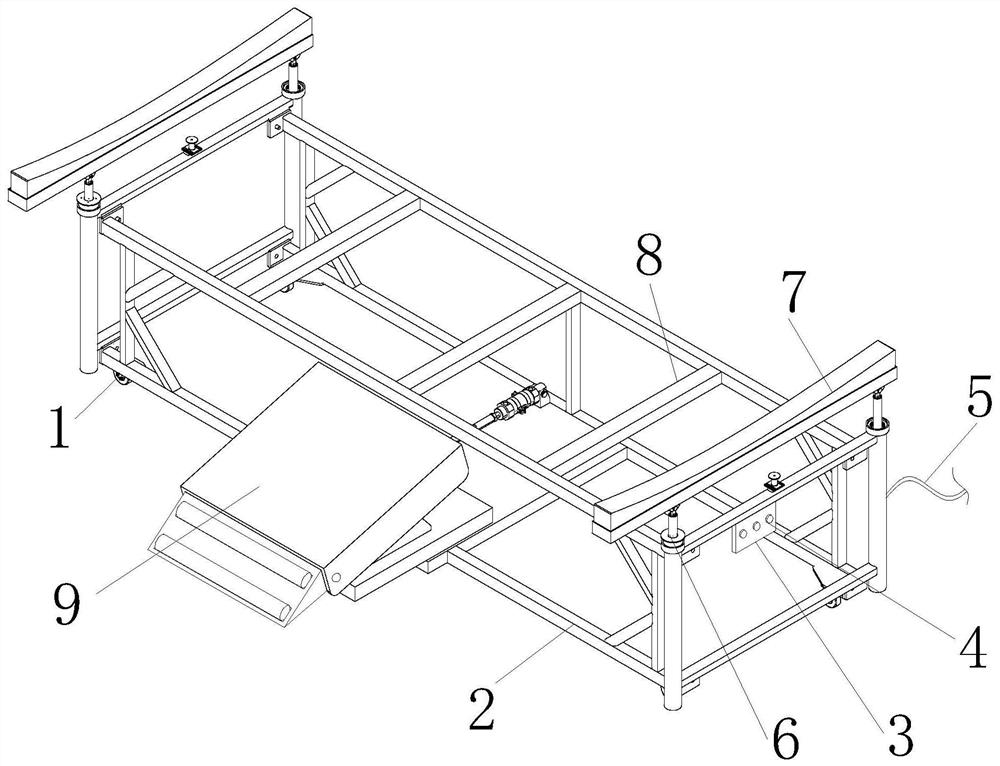
[0029] see figure 1 , the present invention provides a protective fire-fighting equipment placement frame through improvement, including a roller 1, a support frame 2, a vertical bar 6, a protective plate 7, a cross bar 8 and a mobile tilting mechanism 9, the roller 1 and the support frame 2 The four corners of the bottom are fixedly connected, the right end of the support frame 2 is provided with a control panel 3, the front end of the control panel 3 is equipped with a button 4, the moving and tilting mechanism 9 is installed and fixed at the lower end of the support frame 2, and the rear end of the support frame 2 is fixed with a power wire 5. 2 is fixedly connected to the bottom of the vertical bar 6, the end of the vertical bar 6 away from the vertical bar 6 is welded and fixed to the protective plate 7, and the inner side of the top of the support frame 2 is equidistantly distributed with horizontal bars 8.

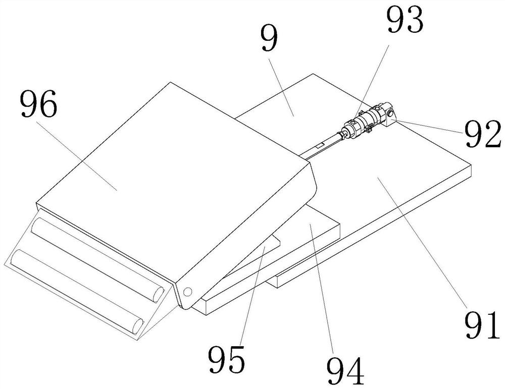
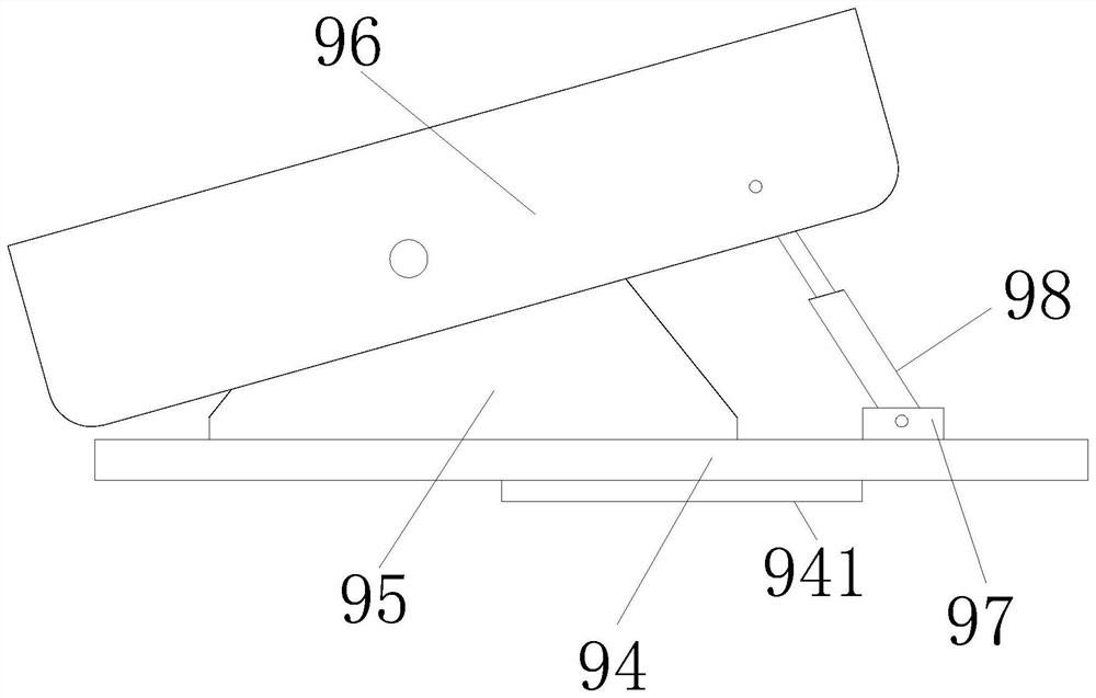
[0030] see figure 2 with image 3 , the present invention p...

Embodiment 2

[0034]The present invention provides a protective fire-fighting equipment placement frame through improvement. There are two guide wheels 965, and the upper ends of the guide wheels 965 are provided with anti-skid lines, which are beneficial to play the role of anti-skid. There are three cross bars 8 distributed equidistantly along the inner upper end of the support frame 2, which is beneficial to play the role of placing fire-fighting equipment.

[0035] The present invention provides a fire-fighting equipment placement rack with strong protection through improvement, and its working principle is as follows;

[0036] First, before use, horizontally place the protective fire-fighting equipment rack so that the roller 1 can support the rack;

[0037] Second, when in use, connect the external power supply through the power lead 5 to provide power to the placement rack;

[0038] Third, when the fire-fighting equipment is to be carried, press the button 4 on the top of the contro...


PUM


Abstract

The invention discloses a fire-fighting equipment placing rack with strong protective property. The fire-fighting equipment placing rack with strong protective property comprises rollers, a support frame, a vertical rod, a protection plate, a cross rod and a moving inclination mechanism. According to the fire-fighting equipment placing rack with strong protective property, by arranging the movinginclination mechanism at the upper end of the support frame, an electric push rod is electrified to work to drive a moving plate to move to the front end of a bottom plate through a guide block, the moving plate is enabled to drive a gear linkage mechanism and an inclined plate to move to the front end of the support frame, and therefore, the advantage that the inclined plate can be quickly drivento move is achieved; and by arranging the gear linkage mechanism at the upper end of the moving inclination mechanism, a motor is powered on to work, a big gear is driven to rotate through a small gear so that the big gear drives an inclining frame to be inclined through a rotating shaft, and then consumption equipment can be moved at the upper end of the inclining frame, and therefore, the advantage that fire-fighting equipment can be guided and conveyed is achieved.

Description

technical field [0001] The invention relates to the related field of fire-fighting equipment placement racks, in particular to a fire-fighting equipment placement rack with strong protection. Background technique [0002] Firefighter equipment usually refers to firefighting tools, equipment used for fire extinguishing, fire prevention and fire accidents, equipment for professional fire extinguishing, in order to do a good job in firefighting work, extinguish fires in time, and prevent accidents, strictly strengthen the management of firefighting facilities and firefighting equipment , People usually place the fire fighting equipment on the shelf for storage. [0003] When taking fire-fighting equipment, it often requires multiple firefighters to cooperate and carry it, which makes it inconvenient to take the fire-fighting equipment. Time-consuming. Contents of the invention [0004] Therefore, in order to solve the above-mentioned shortcomings, the present invention prov...

Claims


Application Information

Patent Timeline
IPC IPC(8): B25H3/04A62C8/00A62C13/78
CPCA62C8/00A62C13/78B25H3/04
Inventor 钟荣鑫
Owner 钟荣鑫
Why Eureka
Try Eureka