Pose tracking method, pose tracking device and electronic equipment

A pose and algorithm technology, applied in the field of computer vision processing, can solve problems such as poor pose tracking robustness and tracking loss.

Pending Publication Date: 2020-11-17
ARCSOFT CORP LTD
View PDF4 Cites 3 Cited by
  • Summary
  • Abstract
  • Description
  • Claims
  • Application Information

AI Technical Summary

Problems solved by technology

[0004] Embodiments of the present invention provide a pose tracking method, a pose tracking device, and electronic

Method used


Image

  • Pose tracking method, pose tracking device and electronic equipment
  • Pose tracking method, pose tracking device and electronic equipment
  • Pose tracking method, pose tracking device and electronic equipment

Examples


Embodiment 1

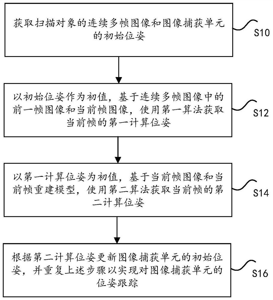
[0056] According to one aspect of the present invention, a pose tracking method is provided. refer to figure 1 , is a flowchart of an optional pose tracking method according to an embodiment of the present invention. Such as figure 1 As shown, the method includes the following steps:

[0057] S10: Acquire continuous multi-frame images of the scanned object and the initial pose of the image capture unit;

[0058] S12: Using the initial pose as an initial value, based on the previous frame image and the current frame image in the continuous multi-frame images, using the first algorithm to obtain the first calculated pose of the current frame;

[0059] S14: Using the first calculated pose as an initial value, based on the current frame image and the current frame reconstruction model in the continuous multi-frame images, use the second algorithm to obtain the second calculated pose of the current frame;

[0060] S16: Update the initial pose of the image capture unit according...

Embodiment 2

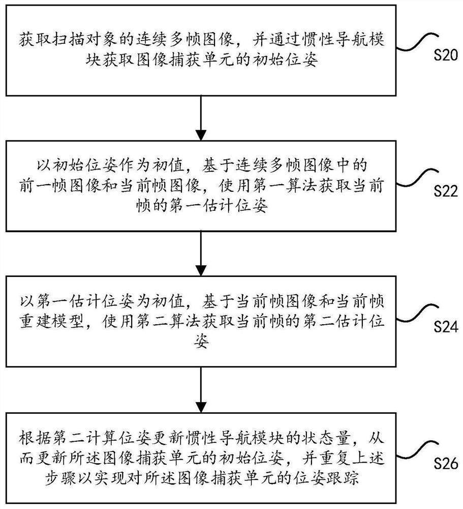
[0077] According to another aspect of the embodiments of the present invention, a pose tracking method based on an inertial navigation module is also provided, so as to further improve the tracking robustness of the image capture unit. refer to figure 2 , is a flow chart of an optional inertial navigation module-based pose tracking method according to an embodiment of the present invention. like figure 2 As shown, the method includes the following steps:

[0078] S20: Obtain continuous multi-frame images of the scanned object, and obtain the initial pose of the image capture unit through the inertial navigation module;

[0079] S22: Using the initial pose as an initial value, based on the previous frame image and the current frame image in the continuous multi-frame images, using the first algorithm to obtain the first calculated pose of the current frame;

[0080] S24: Using the first calculated pose as an initial value, based on the current frame image and the current f...

Embodiment 3

[0094] According to yet another aspect of the embodiments of the present invention, a pose tracking method including relocalization is also provided, which can quickly restore the pose tracking of the image capture unit in the case of tracking loss, and re-estimate the pose of the image capture unit , to further improve the robustness of image capture unit tracking and improve user experience. refer to Figure 5 , is a flow chart of an optional pose tracking method including relocalization according to an embodiment of the present invention. like Figure 5 As shown, the method includes the following steps:

[0095] S50: Obtain continuous multi-frame images of the scanned object, and obtain the initial pose of the image capture unit through the inertial navigation module;

[0096] S52: Using the initial pose as an initial value, based on the previous frame image and the current frame image in the continuous multi-frame images, using the first algorithm to obtain the first ca...


PUM


Abstract

The invention discloses a pose tracking method, a pose tracking device and electronic equipment. The pose tracking method comprises the following steps: acquiring continuous multi-frame images of a scanned object and an initial pose of an image capture unit; taking the initial pose as an initial value, and based on a previous frame image and a current frame image in the continuous multi-frame images, using a first algorithm to obtain a first calculation pose of the current frame; taking the first calculation pose as an initial value, and obtaining a second calculation pose of a current frame by using a second algorithm based on the current frame image and a current frame reconstruction model; and updating the initial pose of an image capture unit according to the second calculation pose, and repeating the above steps to realize pose tracking of the image capture unit. The pose of the image capture unit can be accurately estimated, an approximately accurate pose can be provided when a scanned object deviates from a visual field range, and the pose tracking robustness of the image capture unit is improved.

Description

technical field [0001] The invention relates to computer vision processing technology, in particular to a pose tracking method, a pose tracking device and electronic equipment. Background technique [0002] Three-dimensional reconstruction refers to the construction of a digital three-dimensional model of a real object by obtaining the geometric shape and material of the real object, so as to truly restore the shape of the object. Its input can be images, video streams, and 3D point clouds captured by various types of cameras in real time, or captured images, videos, and 3D point clouds. 3D reconstruction is widely used in computer-aided geometric design, computer animation, computer vision, medical imaging, virtual reality, augmented reality, digital media and other fields. [0003] Camera tracking is the core and most critical algorithm module in 3D reconstruction, which is used to estimate the camera pose at any moment during the shooting process, including spatial 3D po...

Claims


Application Information

Patent Timeline
IPC IPC(8): G06T7/70G06T17/00G06T19/00
CPCG06T7/70G06T17/00G06T19/003G06T19/00G06T2207/10016G06T2207/10028G06T7/246G06T7/292G06T7/30G06T7/74G06T2207/10024G06T2207/30244
Inventor 张龙张超王进
Owner ARCSOFT CORP LTD
Why Eureka
Try Eureka