ORBSLAM2-based unmanned aerial vehicle autonomous navigation method

A technology for autonomous navigation and drones, applied in image data processing, instruments, calculations, etc., can solve problems such as large positioning errors, judging pose deviations, drones hovering in corners and unable to avoid obstacles, etc., to improve convergence Accurate effect of speed and pose

Pending Publication Date: 2021-12-17
NANJING UNIV OF INFORMATION SCI & TECH
View PDF3 Cites 2 Cited by
  • Summary
  • Abstract
  • Description
  • Claims
  • Application Information

AI Technical Summary

Problems solved by technology

[0003] For example, a binocular 3D dense mapping method based on ORB_SLAM2 published in Patent No. CN 108520554 A mainly proposes four ORB (Oriented FAST and Rotated BRIEF) threads for SLAM mapping: tracking thread, local map thread, closed-loop monitoring thread and dense Mapping process, this method puts the ORB feature point extraction and matching process in the tracking process, if the ORB feature points appear in a pile, it will cause a large deviation in the visual odometer to judge the pose, and the ORB feature point is not divided into blocks optimization, it will lead to a large positioning error
[0004] In the existing UAV SLAM system, after extracting ORB feature points in the positioning module, it is necessary to consider the existence of feature points in piles, which affects the estimation of the visual odometry pose. After the dense point cloud image is generated in the mapping module, there is no global optimization. Errors occur when the image is transformed into pixel coordinates. The traditional RRT* algorithm may cause the UAV to hover in the corner and cannot avoid obstacles or the circle around the obstacle is too large when the path planning module is running.

Method used


Image

  • ORBSLAM2-based unmanned aerial vehicle autonomous navigation method
  • ORBSLAM2-based unmanned aerial vehicle autonomous navigation method
  • ORBSLAM2-based unmanned aerial vehicle autonomous navigation method

Examples


Embodiment Construction

[0090] The invention will be described in further detail below in conjunction with the accompanying drawings.

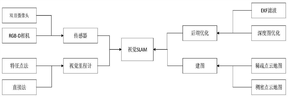
[0091] An autonomous navigation method for UAV based on ORB_SLAM2, such as figure 1 The method includes visual SLAM front-end design, visual SLAM back-end global optimization and mapping, and unmanned aerial vehicle path planning algorithm design.

[0092] (1) Visual SLAM front-end design

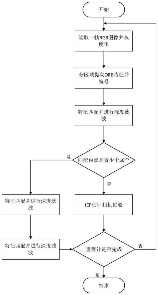
[0093] The visual SLAM front-end design includes ORB feature point extraction and brute force matching, and position estimation based on the ICP algorithm. The overall visual SLAM front-end design process is as follows: figure 2 shown. ORB feature point extraction consists of two parts: FAST corner point and BRIEF descriptor

[0094] FAST corner point is a relatively special pixel point. Local pixel blocks with obvious grayscale changes in the image represent the characteristics of the image. The idea of ​​FAST corner point monitoring process: compare the grayscale of a pixel ...


PUM


Abstract

The invention discloses an ORBSLAM2-based unmanned aerial vehicle autonomous navigation method, and belongs to the field of visual synchronous localization and map construction. The method is mainly composed of visual front-end and visual rear-end global optimization and mapping and three-dimensional path planning. The visual front-end mainly comprises ORB feature point extraction and matching and calculation of a current unmanned aerial vehicle pose by a visual odometer, and the part realizes a positioning function. Visual rear-end global optimization and mapping mainly comprise BA global graph optimization and dense point cloud image mapping, and the part realizes global optimization and mapping functions. Three-dimensional path planning realizes indoor and outdoor obstacle avoidance operation of the unmanned aerial vehicle, and the part realizes a path planning function. ORB pixel points are extracted by using improved FAST angular points, and ORB feature points are subjected to block optimization. Pose estimation is made by using an improved ICP-PnP algorithm.

Description

technical field [0001] The invention relates to an autonomous navigation method for an unmanned aerial vehicle based on ORB_SLAM2, and belongs to the field of visual synchronization positioning and map construction (SLAM). Background technique [0002] Unmanned aerial vehicle has a very wide range of applications in many fields. It is a kind of mobile robot, referred to as UAV (Unmanned Aerial Vehicle, UAV). By carrying a controller on the UAV, people can control the aircraft on the ground. flight. At the same time, the advent of the Simuitaneous Localization and Mapping (SLAM) algorithm is to solve the positioning problem of the robot when there is no GPS signal, and it can also measure the map of the environment. Autonomous navigation of drones relying on RGB-D is mainly divided into three elements: "Where am I?", "What is my environment like?", "How do I go to get to the mission destination?", this The three problems represent respectively: positioning mapping and path ...

Claims


Application Information

Patent Timeline
Patent Type & Authority Applications(China)
IPC IPC(8): G06T7/13G06T7/246G06T7/73G06T7/80
CPCG06T7/13G06T7/248G06T7/74G06T7/80G06T2207/20164G06T2207/30241G06T2207/30244
Inventor 范嘉宇刘云平王炎袁玉雯苏东彦
Owner NANJING UNIV OF INFORMATION SCI & TECH
Why Eureka
Try Eureka