
Terminal equipment adjusting system and method with wireless charging function

A technology of terminal equipment and wireless charging, applied in the direction of circuit devices, electrical components, etc., can solve problems such as inability to increase direct power, damage to equipment storage capacity, and slow wireless charging

Active Publication Date: 2020-11-17
狐灵灵智能科技有限公司
View PDF2 Cites 2 Cited by
  • Summary
  • Abstract
  • Description
  • Claims
  • Application Information

AI Technical Summary

Problems solved by technology

[0007] At present, when the device is wirelessly charged, the wireless charging device is charged according to a fixed current output. When each device is charged according to a fixed current, the terminal device may have a low power level and the device has been performing data transmission. , resulting in too slow wireless charging, or the inability to increase the direct power, resulting in damage to the storage capacity of the device. This application aims to analyze the amount of data transmitted by the terminal device, so as to determine the power consumption of the transmitted data, and intelligently switch the wireless charging mode. charging mode

Method used


Image

  • Terminal equipment adjusting system and method with wireless charging function
  • Terminal equipment adjusting system and method with wireless charging function
  • Terminal equipment adjusting system and method with wireless charging function

Examples


Embodiment 1

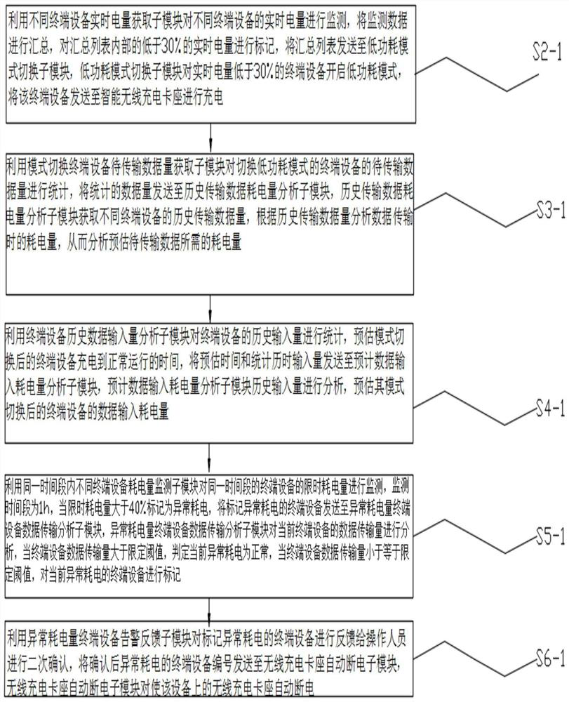
[0074] Embodiment 1: limited conditions, the historical transmission data power consumption analysis sub-module is used to obtain the historical transmission data volume of the terminal equipment, and segment the historical transmission data volume according to each time period for the acquired historical transmission data volume, The time limit of each time period is the same, the amount of transmitted data within each segment is set to 2G, 3.1G, 2.7G, 1.9G, 3.6G, and the power consumption of each time segment detection is set to 4% , 4.7%, 4.4%, 2.8%, 5%, set the mode switching terminal equipment to be transmitted data volume acquisition sub-module statistics of the internal data volume of the terminal equipment to be transmitted is 6.1G, the terminal equipment has the power consumption of equipment operation, set The power consumption during fixed operation is 7%, and the estimated power consumption of the amount of data to be transmitted inside the terminal device is set as...

Embodiment 2

[0077] Example 2: limited conditions, the estimated data input power consumption analysis sub-module is used to obtain the time for the terminal device to be charged to normal operation after mode switching, and the time limit for the terminal device to be charged to normal operation is set to 25 minutes, and a time of 25 minutes is used Segment the historical terminal equipment input volume, set the data input volume in each segment as 1.1G, 0.9G, 1G, 1.5G, 0.6G, and set the current power consumption of data input with the same time limit as 1.5%, 1.3%, 1.4%, 1.7%, 0.9%, set the estimated amount of input data to be J within the Tu time limit when the terminal equipment is charged to normal operation, according to the formula:

[0078]

[0079] It is calculated that the estimated input data volume within the Tu time limit from charging the terminal equipment to normal operation is 1.12G. When setting the data input of the terminal equipment, the power consumption rate of the...


PUM


Abstract

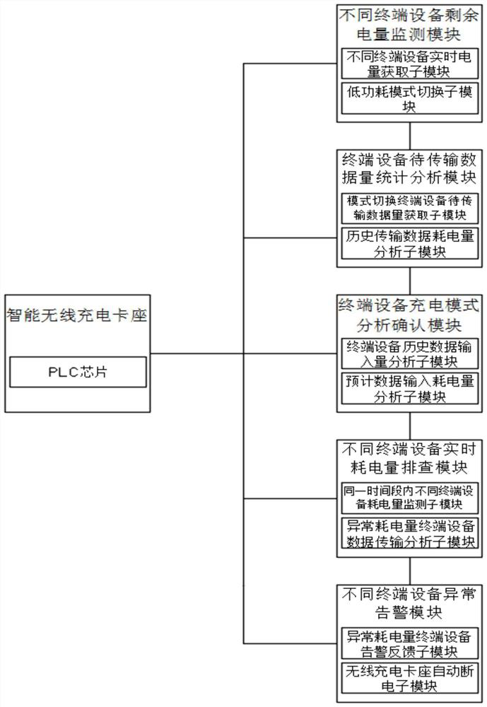
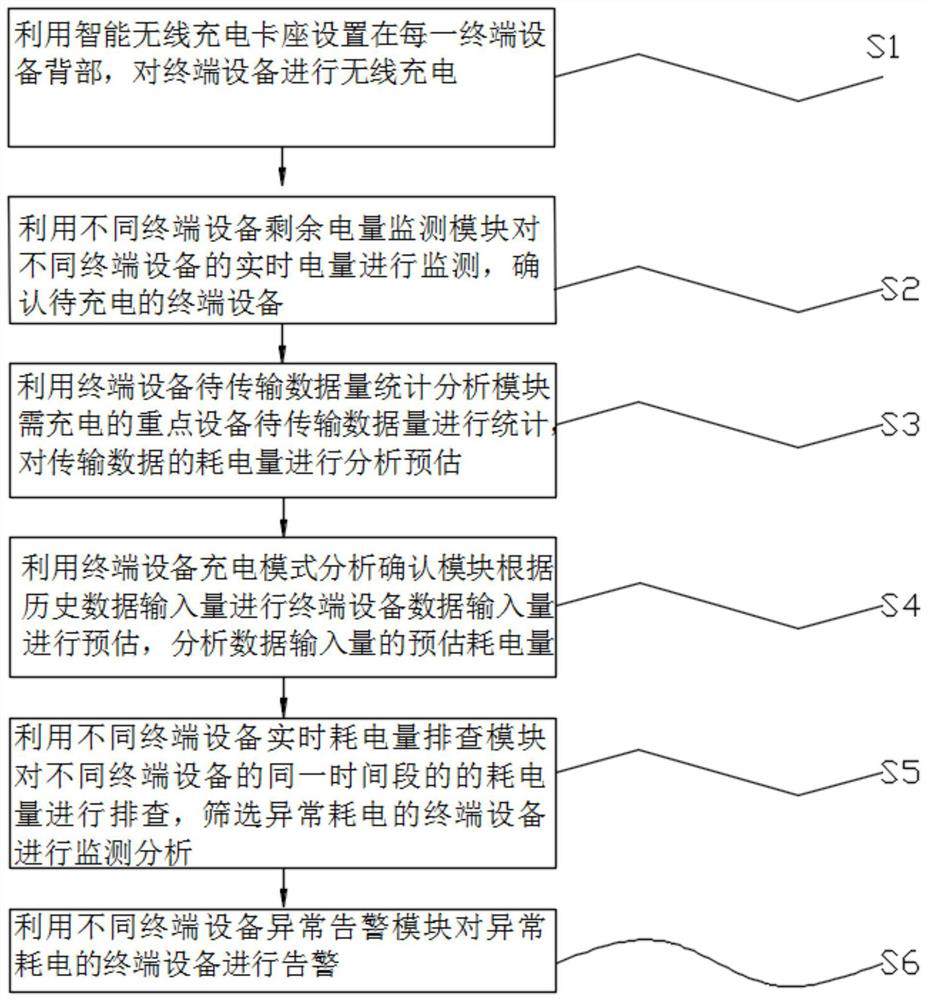
The invention discloses a terminal equipment adjusting system and method with a wireless charging function, an intelligent wireless charging clamping seat is arranged in the system, is arranged at theback of each terminal equipment and is used for wirelessly charging the terminal equipment, and different terminal equipment residual electric quantity monitoring modules are used for monitoring thereal-time electric quantity of different terminal equipment. The terminal equipment to-be-transmitted data volume statistical analysis module is used for counting the to-be-transmitted data volume ofkey equipment needing to be charged and analyzing and estimating the power consumption of transmitted data, and the terminal equipment charging mode analysis confirmation module is used for estimatingthe data input quantity of the terminal equipment according to the historical data input quantity. And the estimated power consumption of the data input quantity is analyzed, the different terminal equipment real-time power consumption checking modules being used for checking the power consumption of different terminal equipment in the same time period, screening the terminal equipment with abnormal power consumption for monitoring and analysis, and the different terminal equipment abnormity warning modules being used for warning the terminal equipment with abnormal power consumption.

Description

technical field [0001] The present invention relates to the technical field of wireless charging, in particular to a terminal device adjustment system and method provided with wireless charging. Background technique [0002] Wireless charging technology originates from wireless power transmission technology, which can be divided into low-power wireless charging and high-power wireless charging. Low-power wireless charging often uses electromagnetic induction, and high-power wireless charging often uses resonance. The power supply equipment (charger) transmits energy to the device that uses the power. The device uses the received energy to charge the battery and at the same time supply itself. for operational purposes. [0003] Because the energy is transmitted between the charger and the electric device with a magnetic field, there is no wire connection between the two, so both the charger and the electric device can have no exposed conductive contacts, and the alternating ...

Claims


Application Information

Patent Timeline
IPC IPC(8): H02J50/80
CPCH02J50/80
Inventor 费希敏
Owner 狐灵灵智能科技有限公司
Learn More