
ZVS control method for active clamp flyback topology adaptive dead time

A flyback topology, dead time technology, applied in control/regulation systems, output power conversion devices, instruments, etc., can solve the problem that the switching power supply turn-on time interval cannot be adaptively changed.

Active Publication Date: 2020-11-17
ANHUI DONGKE SEMICON CO LTD
View PDF9 Cites 11 Cited by
  • Summary
  • Abstract
  • Description
  • Claims
  • Application Information

AI Technical Summary

Problems solved by technology

[0006] The technical problem solved by the present invention is to provide a ZVS control method for active clamp flyback topology self-adaptive dead time, to solve the problem that the switch-on time interval in the switching power supply in the prior art cannot be adaptively changed as the actual application conditions change problem

Method used


Image

  • ZVS control method for active clamp flyback topology adaptive dead time
  • ZVS control method for active clamp flyback topology adaptive dead time
  • ZVS control method for active clamp flyback topology adaptive dead time

Examples


Embodiment Construction

[0026] In order to facilitate the understanding of the present invention, the present invention will be described in more detail below in conjunction with the accompanying drawings and specific embodiments. Preferred embodiments of the invention are shown in the accompanying drawings. However, the present invention can be implemented in many different forms and is not limited to the embodiments described in this specification. On the contrary, these embodiments are provided to make the understanding of the disclosure of the present invention more thorough and comprehensive.

[0027] It should be noted that, unless otherwise defined, all technical and scientific terms used in this specification have the same meaning as commonly understood by those skilled in the technical field of the present invention. Terms used in the description of the present invention are only for the purpose of describing specific embodiments, and are not used to limit the present invention. The term "...


PUM


Abstract

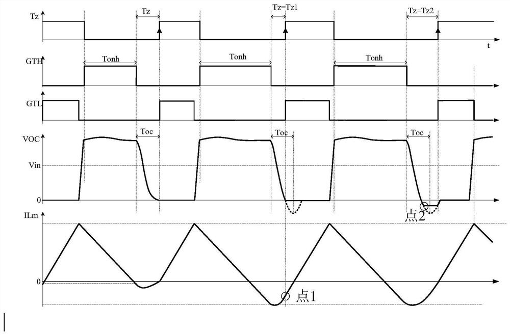
The invention relates to a ZVS control method for active clamp flyback topology self-adaptive dead time, and the method comprises the following steps: setting a control circuit for a switching power supply circuit, detecting current flowing through a primary coil inductor of a transformer and zero-crossing voltage, and further regulating and controlling the conduction duration of a clamp switchingtube and the switching-on time interval of a main switching tube; and realizing the zero-voltage switching-on of the main switching tube. According to the method, the turn-on time interval of the main switching tube can be dynamically adjusted in real time according to different input voltages, output voltages and application parameters, and the interval can reach the optimal value capable of realizing zero-voltage turn-on.

Description

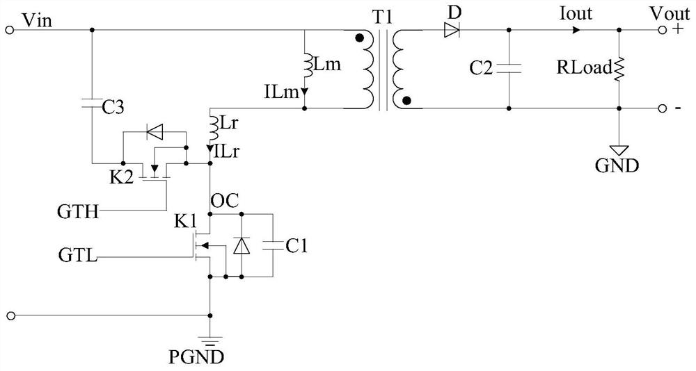
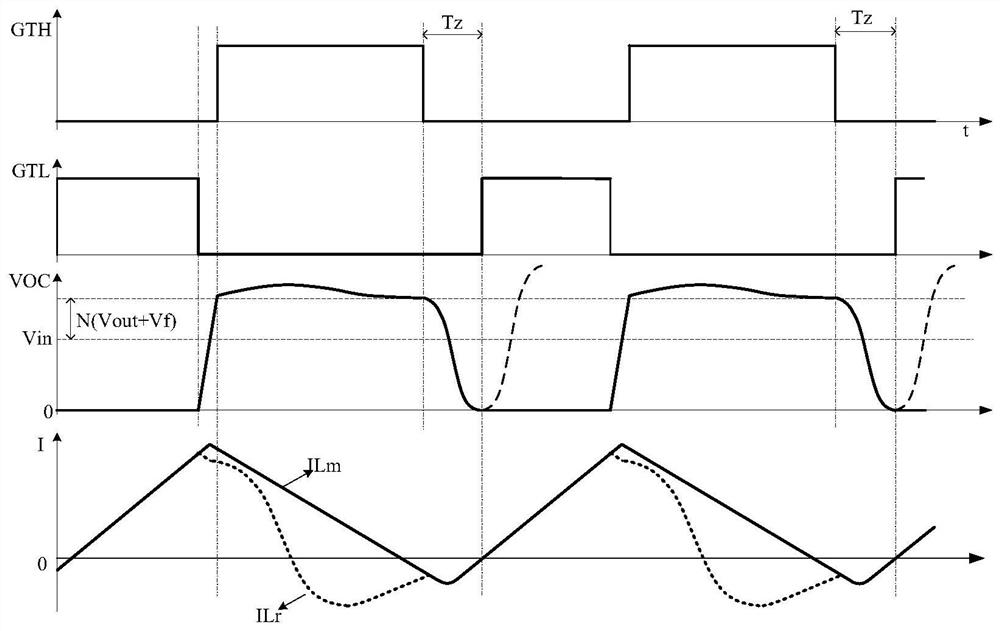
technical field [0001] The invention belongs to the technical field of power supplies, and in particular relates to a ZVS control method for an active clamp flyback topology self-adaptive dead zone time. Background technique [0002] Such as figure 1 Shown is a schematic diagram of an active clamp flyback switching power supply in the prior art. Among them, Vin is the voltage of the input power supply to the reference ground PGND, T1 is the transformer, N is the primary-to-secondary turn ratio of the transformer T1, Lm is the primary side excitation inductance of the transformer T1, ILm is the current of the inductor Lm, and Lr is the leakage inductance of the transformer T1 , ILr is the current of the leakage inductance Lr, K1 is the main switch tube, GTL is the gate control signal of the main switch tube K1, K2 is the clamp switch tube, and C1 is connected to the common terminal OC of the main switch tube K1 and the clamp switch tube K2 For the equivalent capacitance of ...

Claims


Application Information

Patent Timeline
IPC IPC(8): H02M1/08H02M3/335
CPCH02M1/08H02M1/083H02M3/33515H02M3/33523H02M3/33569
Inventor 程兆辉于玮何希见
Owner ANHUI DONGKE SEMICON CO LTD
Learn More