Check patentability & draft patents in minutes with Patsnap Eureka AI!

Combined numerically-controlled machine tool

A CNC machine tool and combined technology, which is applied to the parts of the grinding machine tool, the grinding frame, the grinding bed, etc., can solve the problems of inconvenient use and the combination of two machines, and achieve low transformation costs, The effect of small modification difficulty and simple connection method

Inactive Publication Date: 2020-11-20
李双
View PDF0 Cites 1 Cited by
  • Summary
  • Abstract
  • Description
  • Claims
  • Application Information

AI Technical Summary

Problems solved by technology

[0002] CNC machine tools are relatively important equipment in industrial production. Traditional CNC machine tools are fixedly installed on the workbench with corresponding guide rails, mounting seats, columns, and cutting tools. The size of the workbench is designed to match the corresponding CNC machine tools. The size of the workbench is also fixed; in the actual work process, the CNC machine tool can be assembled and used according to the work needs, for example, the combination of the cutting machine tool and the grinding machine tool can achieve the effect of cutting and grinding continuous work, but because the workbench The size and structure of the machine are fixed. The traditional combined use can only be to place the two machines close together, and then the staff will connect them in an agreed way. It is impossible to combine the two machines together by splicing and transformation. Therefore, It is very inconvenient to use

Method used


Image

  • Combined numerically-controlled machine tool
  • Combined numerically-controlled machine tool
  • Combined numerically-controlled machine tool

Examples


Embodiment Construction

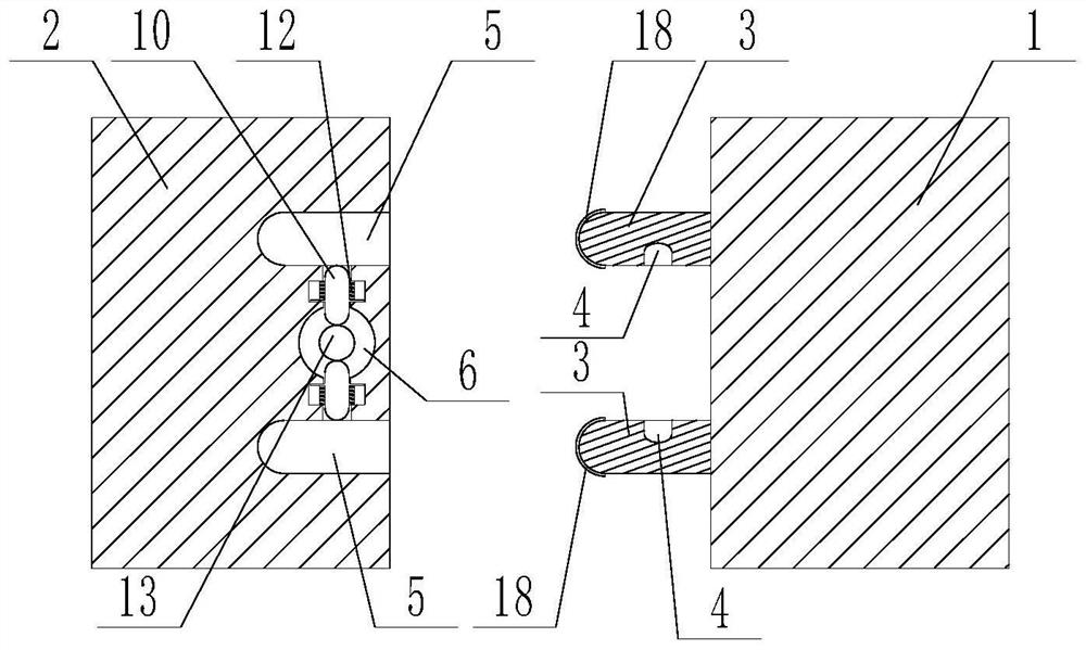
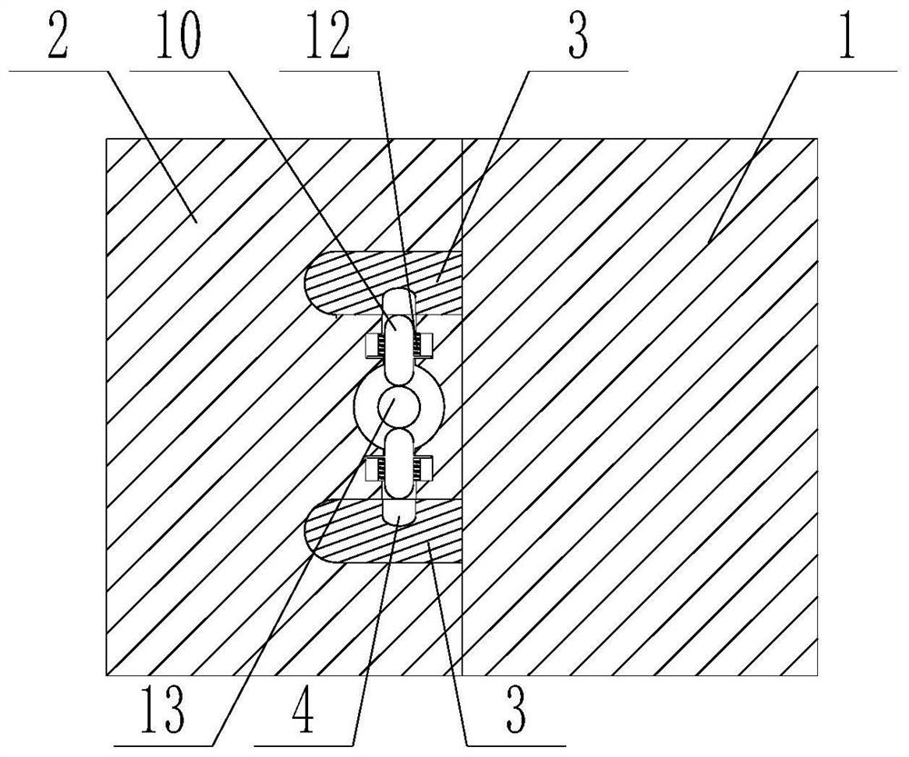
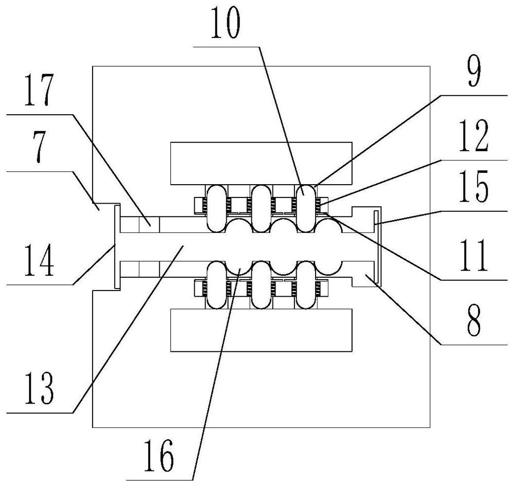
[0027] The present invention is specifically described below in conjunction with accompanying drawing, as Figure 1-4 shown;

[0028] The invention of the present application lies in that two protrusions 3 are arranged on the side surface of workbench one, and the two protrusions are distributed on the side surface of workbench one up and down, and the two protrusions are vertically Alignment, grooves 4 are provided on the opposite side surfaces of the two protrusions, the positions of the two grooves correspond up and down, and the front ends of the protrusions are arc-shaped surfaces;

[0029] The invention of the present application is also that two slots 5 are arranged on the side surface of the workbench 2, the positions of the slots correspond to the positions of the protrusions one by one, and the protrusions can be inserted into the corresponding slots, so A socket 6 is provided in the workbench 2, and the socket communicates with the other side surface adjacent to th...


PUM


Abstract

The invention discloses a combined numerically-controlled machine tool which comprises a workbench I and a workbench II. A numerically-controlled machine tool structure is fixedly installed on the upper surfaces of the workbench I and the workbench II, two protrusions are arranged on the side surface of the workbench I, the two protrusions are distributed on the side surface of the workbench I ina one-upper and the-other-lower mode, the two protrusions are aligned in a vertical direction, grooves are formed in the opposite side surfaces of the two protrusions, the positions of the grooves correspond up and down, and the front end surfaces of the protrusions are arc surfaces. The combined numerically-controlled machine tool has the beneficial effects that the connection structure is simpleand the connection mode is flexible.

Description

technical field [0001] The invention relates to the technical field of numerical control machine tool transformation, in particular to a combined numerical control machine tool. Background technique [0002] CNC machine tools are relatively important equipment in industrial production. Traditional CNC machine tools are fixedly installed on the workbench with corresponding guide rails, mounting seats, columns, and cutting tools. The size of the workbench is designed to match the corresponding CNC machine tools. The size of the workbench is also fixed; in the actual work process, the CNC machine tool can be assembled and used according to the work needs, for example, the combination of the cutting machine tool and the grinding machine tool can achieve the effect of cutting and grinding continuous work, but because the workbench The size and structure of the machine are fixed. The traditional combined use can only be to place the two machines close together, and then the staff ...

Claims


Application Information

Patent Timeline
Patent Type & Authority Applications(China)
IPC IPC(8): B23Q1/00B23Q1/25B24B41/00B24B41/02
CPCB23Q1/00B23Q1/25B24B41/00B24B41/02
Inventor 李双
Owner 李双
Features
  • R&D
  • Intellectual Property
  • Life Sciences
  • Materials
  • Tech Scout
  • Unparalleled Data Quality
  • Higher Quality Content
  • 60% Fewer Hallucinations
Learn More