Eureka AIR delivers breakthrough ideas for toughest innovation challenges, trusted by R&D personnel around the world.

High-speed stacking machine for tires and stacking method thereof

A palletizer and tire technology, which is applied to conveyors, depalletizing of objects, conveyor objects, etc., can solve the problems of high maintenance cost, increased investment cost, complex structure, etc., and achieve easy maintenance, simple structure and low cost. Effect

Inactive Publication Date: 2016-12-07
湖南伍扬工业科技有限公司
View PDF9 Cites 9 Cited by
  • Summary
  • Abstract
  • Description
  • Claims
  • Application Information

AI Technical Summary

Problems solved by technology

[0005] 1. High cost: One tire needs to be supplied when the cycle time in the tire assembly process reaches 3 to 15 seconds. Most enterprises use imported manipulators to realize the palletizing operation of the whole stack of tires. In one project, 3 to 4 manipulators are needed. , which greatly increases the investment cost of the enterprise
[0006] 2. At present, there are some tire palletizing equipment on the market that are cheaper than manipulators, but it takes about 20 seconds to stack a tire, which has low efficiency, complex structure and high maintenance cost.

Method used


Image

  • High-speed stacking machine for tires and stacking method thereof
  • High-speed stacking machine for tires and stacking method thereof
  • High-speed stacking machine for tires and stacking method thereof

Examples


Embodiment Construction

[0033] The present invention will be further described in detail below in conjunction with the accompanying drawings and specific embodiments.

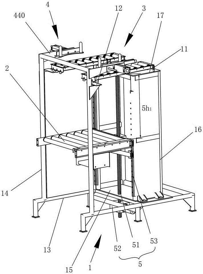
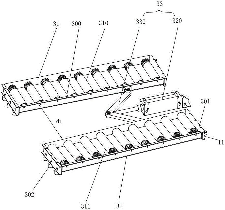
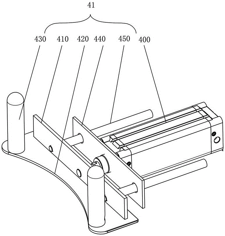
[0034] Such as Figure 1 to Figure 6 As shown, the tire high-speed palletizer of the present embodiment includes a frame 1, a stacking trolley 2, and a material receiving mechanism 3 installed on the frame 1, a tire clamping mechanism 4 and a lifting mechanism 5, and the material receiving mechanism 3 It includes a left material receiving trolley 31, a right material receiving trolley 32, and an opening and closing assembly 33 for driving the left material receiving trolley 31 and the right material receiving trolley 32 to move closer to or away from each other. The tire clamping mechanism 4 is located on the upper side of the material receiving mechanism 3. The palletizing trolley 2 is located on the lower side of the material receiving mechanism 3, and the lifting mechanism 5 is connected with the palletizing trolley 2. The tire hig...


PUM


Abstract

The invention provides a high-speed stacking machine for tires. The high-speed stacking machine comprises a rack, a stacking trolley, and a material receiving mechanism, a tire clamping mechanism and a hoisting mechanism which are assembled on the rack; the material receiving mechanism comprises a left material receiving trolley, a right material receiving trolley and an opening and closing assembly; the tire clamping mechanism is located at the upper side of the material receiving mechanism; the stacking trolley is located at the lower side of the material receiving mechanism; and the hoisting mechanism is connected with the stacking trolley. A stacking method comprises the following steps: S1: receiving the tires, conveyed by a former procedure, by the material receiving mechanism and conveying the tires to the tire clamping mechanism; tightly clamping the tires by the tire clamping mechanism; S2: driving the left material receiving trolley and the right material receiving trolley to get far away from each other through the opening and closing assembly until the distance between the left material receiving trolley and the right material receiving trolley is not smaller than the diameter of the tires; S3: releasing the tires by the tire clamping mechanism and enabling the tires to fall onto the stacking trolley from the left material receiving trolley to the right material receiving trolley; S4: driving the stacking trolley to descend by the hoisting mechanism, wherein the descending distance is not smaller than the thickness of the tires; driving the left material receiving trolley and the right material receiving trolley to get close by the opening and closing assembly; and S5: repeating S1 to S4 until the quantity of the tires reaches a designed value and conveying a tire stack to a next procedure through the stacking trolley.

Description

technical field [0001] The invention relates to tire palletizing technology, in particular to a tire high-speed palletizer and a palletizing method thereof. Background technique [0002] The rapid development of the automobile industry has brought opportunities and challenges to the development of auto parts logistics. The lean logistics model is one of the representative models of auto parts logistics. However, in practice, problems such as the application method, effect, applicability and implementation of various special machinery in the lean logistics model come one after another. [0003] Tires are key components in the automobile manufacturing process. After the automobile manufacturing industry implements a lean logistics management model, it is required that parts and components be directly and accurately supplied to the automobile assembly line. It needs to fully cooperate with the time and rhythm of the assembly plant, match the model and other data. The tire ass...

Claims


Application Information

Patent Timeline
Patent Type & Authority Applications(China)
IPC IPC(8): B65G59/02B65G47/06
CPCB65G59/02B65G47/06B65G2201/0273
Inventor 胡小辉全小军黄强
Owner 湖南伍扬工业科技有限公司
Why Eureka
Eureka Blog
Learn More