On-site absorption spectrum gas analysis system

A gas analysis system and analysis system technology, applied in the field of spectrum analysis, can solve the problems of increasing the complexity of the system, increasing the number of reflective surfaces, increasing the optical noise, etc., to reduce the optical etalon noise, reduce the optical etalon noise, and improve the measurement accuracy. Effect

Inactive Publication Date: 2011-06-22
FOCUSED PHOTONICS
View PDF7 Cites 9 Cited by
  • Summary
  • Abstract
  • Description
  • Claims
  • Application Information

AI Technical Summary

Problems solved by technology

In addition, affected by various environmental factors (temperature changes, mechanical vibrations, etc.), the distance between the surfaces of optical components often changes slightly; due to the short wavelength of the laser, small changes will cause phase changes between multiple beams. The obvious change of the difference, thereby significantly changing the transmittance change caused by the above-mentioned multi-beam interference, that is to say, the distribution of etalon noise with the optical frequency will be affected by various environmental factors, which will bring difficulties to accurate gas parameter analysis.
image 3 The gas single-line absorption spectrum measured by the analysis system without etalon noise is given, and the signal-to-noise ratio of the gas single-line absorption spectrum measured with etalon noise will decrease significantly, as shown in Figure 4 shown
For fixed-wavelength measurement methods, small wavelength shifts or changes in environmental factors will also cause changes in the apparent transmittance of the optical system, thereby affecting measurement accuracy
[0007] There are some deficiencies in the above-mentioned analysis system: 1) The structure is relatively complicated, and a converging lens is used to converge the divergent light, and at the same time, tempered glass is required to realize explosion-proof; due to the use of multiple optical components, the number of reflective surfaces is increased, and the etalon is increased. Optical noise reduces the measurement accuracy and measurement sensitivity; 2) When measuring the concentration of some media, such as measuring the concentration of trace moisture and oxygen, due to the semiconductor laser, the converging lens, the flameproof glass, the light receiving device, the convergence There are many spaces between the lens and the flameproof glass. If there are gas components to be measured in these spaces, it will affect the measurement. The current method is to either use nitrogen purging or nitrogen filling. To avoid the existence of these measured gases in these spaces; but purging increases the complexity of the system, and the potting method will produce greater measurement inaccuracy when leakage occurs, especially when the concentration of the measured medium is low, such as The order of ppm, therefore, both the light emitting unit 1 and the light receiving unit 2 need to be strictly sealed, and the requirements for leak prevention are high, which further increases the complexity of system design and manufacturing
[0010] This system can realize on-site calibration, but the structure is complicated. For example, in the light emitting unit, the light emitted by a light source is reflected into two beams of parallel light after passing through the concave mirror, and the two beams of parallel light are reflected by the concave mirror in the light receiving unit. Into a receiver, which requires high machining and assembly accuracy; moreover, calibration and measurement need to be carried out independently in two pipes, which cannot effectively use the measurement pipe for calibration, resulting in increased difficulty in installation and commissioning; Yes, when calibrating, it is necessary to block the measuring beam well, otherwise the measuring beam will enter the optical receiver, reducing the calibration accuracy

Method used


Image

  • On-site absorption spectrum gas analysis system
  • On-site absorption spectrum gas analysis system
  • On-site absorption spectrum gas analysis system

Examples


Embodiment 1

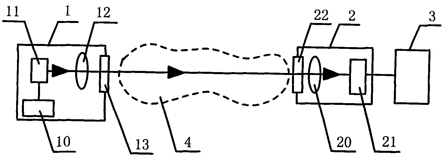
[0054] Such as Image 6 As shown, a semiconductor laser absorption spectrum trace water analysis system is used to detect the concentration of trace water in the measured gas 4 and also meet the explosion-proof requirements. The analysis system includes a light emitting unit 1 , a light receiving unit 2 and a signal analysis unit 3 , and the light emitting unit 1 and the light receiving unit 2 are installed on both sides of the measured gas 4 .

[0055] The light emitting unit 1 includes a housing, a semiconductor laser 11 and its driving circuit 10, a first converging lens 14 and a sleeve 5, and the semiconductor laser 11 and the first converging lens 14 are installed in the sleeve 5, wherein The semiconductor laser 11 is mounted on a laser mount 15 . The driving circuit 10 of the semiconductor laser 11 is installed in the casing. The sleeve and the first converging lens 14 are sealed by a sealing member such as an O-ring 16 , and a lens fastener 17 is installed at the fron...

Embodiment 2

[0074] Such as Figure 7 As shown, a semiconductor laser absorption spectrum trace hydrogen sulfide analysis system is used to detect the concentration of trace hydrogen sulfide, and it also meets the explosion-proof requirements. The difference with embodiment 1 is:

[0075] 1. If Figure 8 As shown, a calibration chamber 6 is provided at the spherical end of the second converging lens. One end of the calibration chamber 6 is closed and has a bevel, and the other end is open, and is sealed and connected with the spherical end of the second converging lens. The calibration chamber 6 is closed with carbon monoxide gas of known concentration.

[0076] 2. The A-A section of the middle part of the first and second converging lenses is a square, such as Figure 9 As shown, the diameter of the smallest covering circle of the square is 40 mm.

[0077] 3. The calibration chamber is filled with carbon monoxide gas of known concentration.

[0078] 4. The central wave number used is...

Embodiment 3

[0080] A semiconductor laser absorption spectrum trace water analysis system is used to detect the concentration of trace gaseous water and also meets the explosion-proof requirements. The difference with embodiment 1 is:

[0081] 1. If Figure 10As shown, the light-emitting unit 1 and the light-receiving unit are on the same side of the measured gas 4, and the light emitted by the light-emitting unit 1 passes through the converging lens 14, the calibration chamber 7, and the measured gas 4 and is reflected by the mirrors 30 and 31. After that, it passes through the measured gas 4, the converging lens 23, and finally is received by the photoelectric sensor 21.

[0082] 2. The A-A section of the middle part of the first and second converging lenses is elliptical, such as Figure 11 As shown, the diameter of the minimum coverage circle of the ellipse is 45mm, and the thickness of the first and second converging lenses (the chief ray optical path of the laser beam in the first ...


PUM

PropertyMeasurementUnit
thicknessaaaaaaaaaa
diameteraaaaaaaaaa
diameteraaaaaaaaaa

Abstract

The invention discloses an on-site absorption spectrum gas analysis system. The system comprises a light transmitting unit, a light receiving unit and a signal analysis unit, wherein the light transmitting unit comprises a light source and a converging lens. The system is characterized in that: one end of the converging lens back to the light source is provided with an arc surface; the arc surface end of the converging lens is provided with a calibration chamber of which one end is provided with an opening and the other end is closed; the opening end is hermetically connected with the converging lens; an A-A section on the middle part of the converging lens is in any geometrical shape; and light emitted by the light source passes through the converging lens and the calibration chamber and enters a medium to be measured. The system has the advantages of real-time on-line calibration, high measuring accuracy and measuring sensitivity, simple and reliable structure, easily realized explosion isolation function, no need of blowing, low sealing requirement and the like, and is convenient to manufacture.

Description

technical field [0001] The invention relates to spectrum analysis, in particular to an in-situ absorption spectrum gas analysis system. Background technique [0002] The on-site gas analysis system is different from the traditional sampling method gas analysis system. It does not require sampling and pretreatment process, overcomes many defects of the traditional sampling method gas analysis system, and has the advantages of simple system, high reliability, fast measurement response speed, and analysis It has the advantages of high precision, can measure the concentration and speed of gas, and has been widely used in modern industry, scientific research, environmental protection and other fields. On-site gas analysis systems can be implemented using a variety of absorption spectroscopy techniques, such as non-dispersive infrared spectroscopy (NDIR) technology, differential optical absorption spectroscopy (DOAS) technology, and tunable semiconductor laser absorption spectrosc...

Claims


Application Information

Patent Timeline
Patent Type & Authority Applications(China)
IPC IPC(8): G01N21/31G01N21/39
Inventor 张文艳周新吴国凯俞大海马海波
Owner FOCUSED PHOTONICS
Why Eureka
Try Eureka