Movable toothed rail conversion device and system for toothed rail turnout zone

A conversion device and conversion system technology, which is applied to tracks, locking mechanisms for turnouts, roads, etc., can solve the problems of unreliable position status detection and difficult maintenance, and achieve safe and reliable position status detection, easy inspection, and convenient maintenance Effect

Active Publication Date: 2020-11-20
CHINA RAILWAY ERYUAN ENG GRP CO LTD
View PDF7 Cites 5 Cited by
  • Summary
  • Abstract
  • Description
  • Claims
  • Application Information

AI Technical Summary

Problems solved by technology

[0004] The purpose of the present invention is to overcome the above-mentioned deficiencies in the prior art that the movable cog rail switching device of the tooth track fork area

Method used


Image

  • Movable toothed rail conversion device and system for toothed rail turnout zone
  • Movable toothed rail conversion device and system for toothed rail turnout zone
  • Movable toothed rail conversion device and system for toothed rail turnout zone

Examples


Embodiment 1

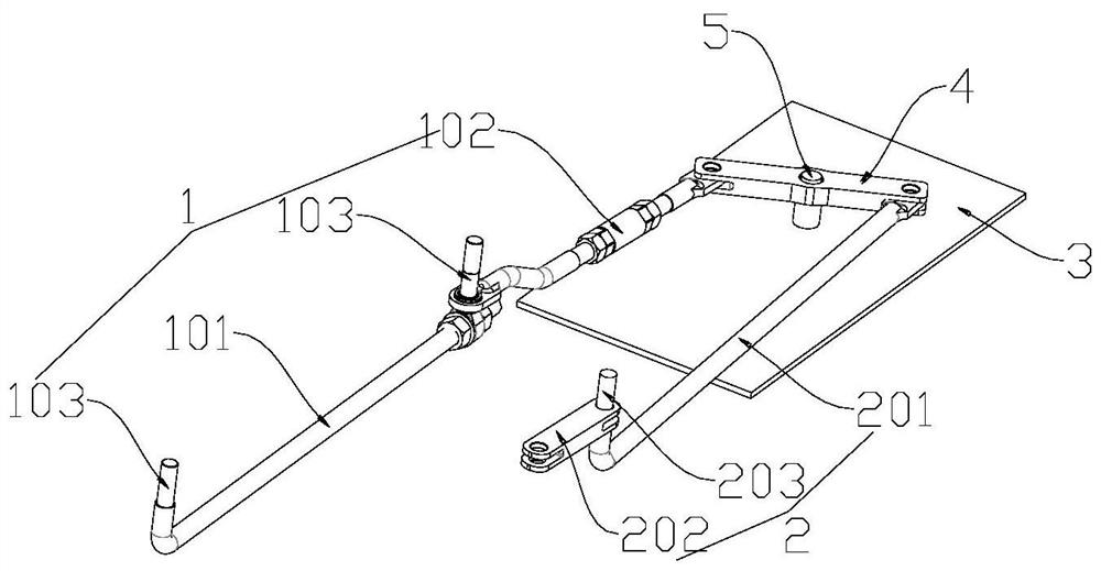
[0037] Such as figure 1As shown, a movable cog rail conversion device for the cogged track fork area includes a rotating rod 4, which is located outside the basic track, one end of the rotating rod 4 is hinged to the outer cog rail connecting rod 1, and the other end is connected to the inner side The rack connecting rod 2 is hinged, the outer rack connecting rod 1 is used to connect the outer movable rack, the inner rack connecting rod 2 is used to connect the inner movable rack, and the two outer movable racks The connecting point with the outer cog rail coupling rod 1 is located on the same side of the rotating rod 4 , and the connecting points of the two inner movable cog rails and the inner rack rail connecting rod 2 are located on the same side of the rotating rod 4 .

[0038] Specifically, the rotating rod 4 is arranged on the fixed plate 3 , and the fixed plate 3 is provided with a third mounting post 5 , and the hinge hole in the middle of the rotating rod 4 is hinged...

Embodiment 2

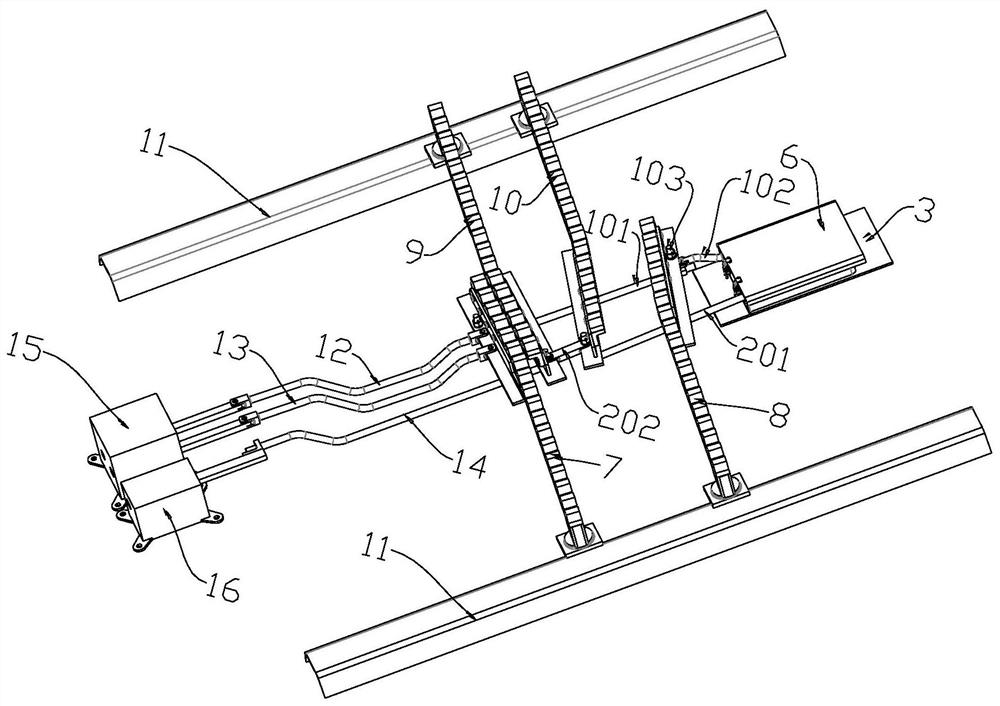
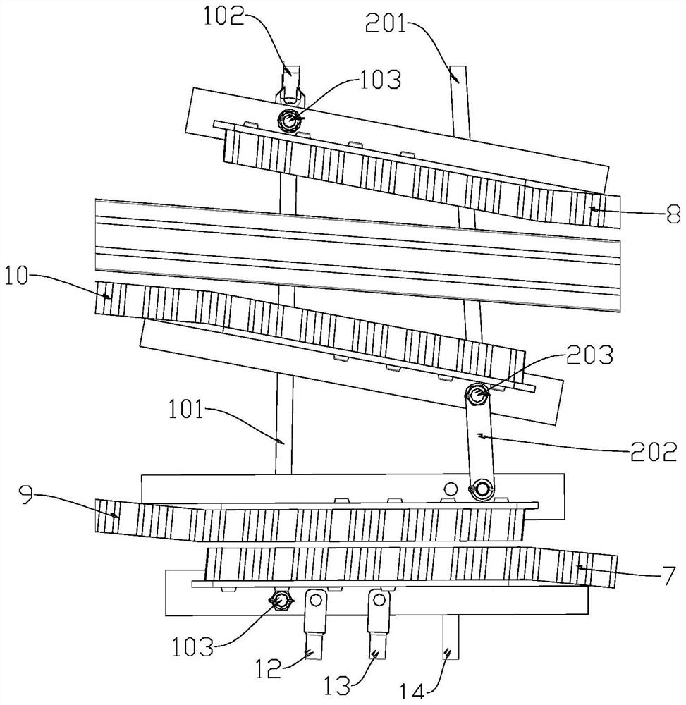
[0040] Such as figure 2 As shown, a movable cog rail conversion system for the cog track fork area includes a power device and a detection device, including a movable cog rail conversion device for the cog track fork area as described in Embodiment 1, and the power device is connected to The outer movable rack at the end of the outer rack coupling rod 1 or the inner movable rack at the end of the inner rack coupling rod 2, the detection device is connected to the inner movable rack located at the end of the inner rack coupling rod 2 The outer movable rack of the rail and the outer rack coupling rod 1 end.

[0041] Specifically, the power device is a turning and withdrawing machine 15, and the detection device is a close-fit checker 16. The turning and withdrawing machine 15 includes a turning and withdrawing machine action lever 12 and a turning and withdrawing machine indicating lever 13. The close-fit inspection The device 16 includes a snugness checker indicating the rod ...


PUM


Abstract

The invention relates to the technical field of toothed rail traffic engineering equipment and in particular relates to a movable toothed rail conversion device for a toothed rail turnout zone. The device comprises a rotating rod and the rotating rod is positioned on the outer side of a basic rail; one end of the rotating rod is hinged to an outer side toothed rail connecting rod, and the other end of the rotating rod is hinged to an inner side toothed rail connecting rod. The outer side toothed rail connecting rod is used for being connected with an outer side movable toothed rail. The innerside toothed rail connecting rod is used for being connected with an inner side movable toothed rail. Two connecting points of the outer side movable toothed rail and the outer side toothed rail connecting rod are located on the same side of the hinge point of the rotating rod and the outer side toothed rail connecting rod, and two connecting points of the inner side movable toothed rail and the inner side toothed rail connecting rod are located on the same side of the hinge point of the rotating rod and the inner side toothed rail connecting rod. By adopting the device, the number of detection devices can be reduced, position state detection is safe and reliable, and maintenance is convenient.

Description

technical field [0001] The invention relates to the technical field of cog rail traffic engineering equipment, in particular to a movable cog rail conversion device and a system for a cog track branch area. Background technique [0002] Chinese patent application number 201911008238.8 discloses a movable rack structure, which can effectively realize the consistency and continuity of the rack structure in the turnout section. [0003] Chinese patent application number 201911007242.2 and application number 201911007252.6 respectively disclose two different movable rack conversion devices, which all have the following disadvantages: 1. The outer movable rack and the inner movable rack are connected in parallel, If a movable rack breaks or deforms, the force may continue to be transmitted, so it is necessary to add multiple detection devices, which increases the cost, and the closed-loop control cannot be formed between each detection device; 2. The rotating structure is located...

Claims


Application Information

Patent Timeline
IPC IPC(8): B61L5/10B61L5/00E01B25/06E01B25/04
CPCB61L5/10B61L5/00E01B25/06E01B25/04
Inventor 王坚强杨岗卢剑锋杨吉忠陈志辉邹少文陈德伟龙旭杨捷余颜丽王栋翟永强易立富王海波王志强姚小军王孔明虞凯刘孜学吴晓王梓丞谭冠华汪峥范琪陈庆
Owner CHINA RAILWAY ERYUAN ENG GRP CO LTD
Why Eureka
Try Eureka