
Miniature sludge solid-liquid separation device

A technology for solid-liquid separation and sludge, which is applied in the fields of sludge treatment, water/sludge/sewage treatment, chemical instruments and methods, etc. It can solve the problems of reduced efficiency of sewage separation equipment and blockage of pipes, and improve the overall fluency. , The effect of preventing sediment blockage and facilitating disassembly and cleaning

Pending Publication Date: 2020-11-20
SHAANXI UNIV OF SCI & TECH
View PDF0 Cites 0 Cited by
  • Summary
  • Abstract
  • Description
  • Claims
  • Application Information

AI Technical Summary

Problems solved by technology

[0003] Aiming at the technical problems existing in the prior art, the present invention provides a micro-sludge solid-liquid separation device to solve the problem of mud and sand often adhering to the inner wall of the pipeline in the treatment of mud-water mixture in the prior art, which may easily cause pipeline blockage. Technical Problems of Reduced Efficiency of Sewage Separation Equipment

Method used


Image

  • Miniature sludge solid-liquid separation device
  • Miniature sludge solid-liquid separation device
  • Miniature sludge solid-liquid separation device

Examples


Embodiment

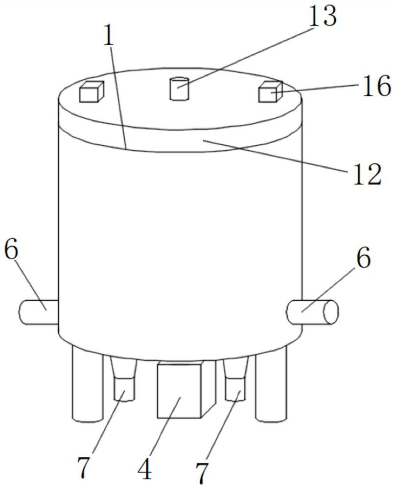
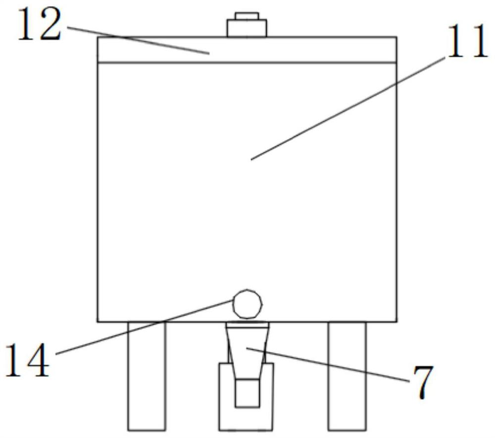
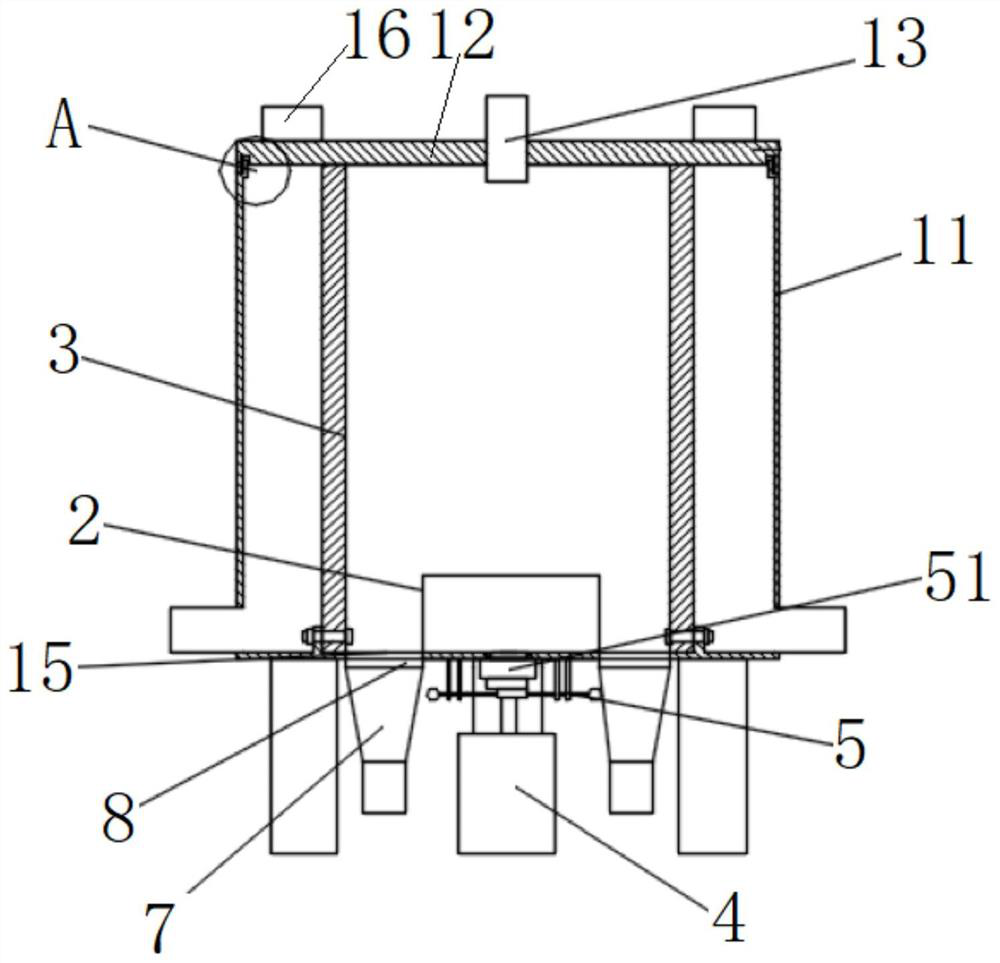
[0041] This embodiment provides a micro-sludge solid-liquid separation device, including a box body, water outlet pipes are arranged on both sides of the bottom of the box body, and a box cover is installed on the top of the box body; a sewage inlet is opened in the center of the top of the box cover ; There is a spiral dragon installed inside the box body, the input end of the spiral dragon is fixedly connected to the rotating shaft, and the rotating shaft runs through the bottom of the box body to connect with the output end of the drive motor; there are screens installed around the spiral dragon, and there are two holes at the bottom of the box inside the screen. The sand outlet is connected with the sand outlet pipe through the sand outlet valve; the box body on one side of the sand outlet pipe is equipped with an impact ball, and the impact ball is fixedly connected to one end of the slide bar, and the slide bar is slidingly sleeved with two a limit sleeve, and the other e...


PUM


Abstract

The invention discloses a miniature sludge solid-liquid separation device, which comprises a box body, a spiral auger is installed in the center of the interior of the box body, a driving motor is fixedly arranged at the bottom of the box body, and the output end of the driving motor is connected with the input end of the spiral auger through a rotating shaft; a screen is arranged on the peripheryof the spiral auger, and the interior of the box body is divided into a sludge area and a sewage area through the screen; a sewage inlet is formed in the center of the upper end of the box body and is communicated with the sludge area; water outlets are formed in the bottoms of the two sides of the box body and communicate with the sewage area; sand outlets are respectively formed in two sides ofthe bottom of the box body and are communicated with the sludge area; the spiral auger is arranged in the box body, the driving motor is used for driving the spiral auger to rotate, sludge water generates centrifugal force through rotation of the spiral auger, and sludge and water in the sludge water are separated; sewage screened by the screen flows out from the water outlets; and silt falls down through a silt outlet formed in the bottom of the sludge area, so that the silt in the sludge water is effectively separated.

Description

technical field [0001] The invention belongs to the technical field of solid-liquid separation of sludge, in particular to a micro-solid-liquid separation device for sludge. Background technique [0002] In the treatment of mud-water mixture, because the separated silt has high water content and high viscosity, it often adheres to the inner wall of the pipeline, so the solid silt cannot be discharged in a timely and effective manner, which will cause pipeline blockage and sewage during production. The efficiency of the separation equipment is reduced, the energy consumption is increased, and the production cost is increased. Therefore, it is necessary to design a sludge solid-liquid separation device. Contents of the invention [0003] Aiming at the technical problems existing in the prior art, the present invention provides a micro-sludge solid-liquid separation device to solve the problem of mud and sand often adhering to the inner wall of the pipeline in the treatment o...

Claims


Application Information

Patent Timeline
IPC IPC(8): C02F11/125
CPCC02F11/125
Inventor 张宏李自改弓超
Owner SHAANXI UNIV OF SCI & TECH
Learn More