A turnbuckle screw displacement tension automatic adjustment mechanism and its application method

A turnbuckle screw, automatic adjustment technology, applied in building construction, building material processing, construction, etc., can solve the problems of poor consistency of wire rope tension, high labor intensity, and hidden dangers of accidents.

Active Publication Date: 2021-09-14
CHINA MCC17 GRP
View PDF3 Cites 0 Cited by
  • Summary
  • Abstract
  • Description
  • Claims
  • Application Information

AI Technical Summary

Problems solved by technology

In the actual construction process, workers usually rely on pipe wrench or crowbar to adjust the turnbuckle screws to realize the tightness of the steel wire rope. The adjustment process is labor-intensive, the consistency of the tension of the steel wire rope is poor, the force is uneven, and there are hidden dangers of accidents.

Method used


Image

  • A turnbuckle screw displacement tension automatic adjustment mechanism and its application method
  • A turnbuckle screw displacement tension automatic adjustment mechanism and its application method
  • A turnbuckle screw displacement tension automatic adjustment mechanism and its application method

Examples


Embodiment 1

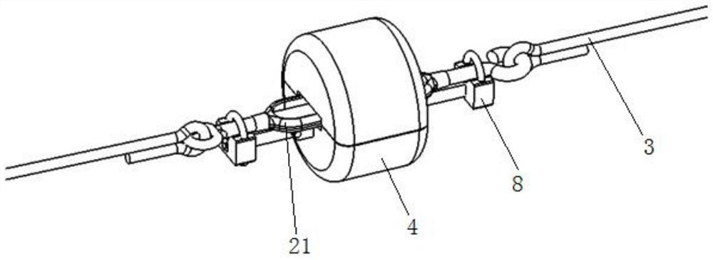
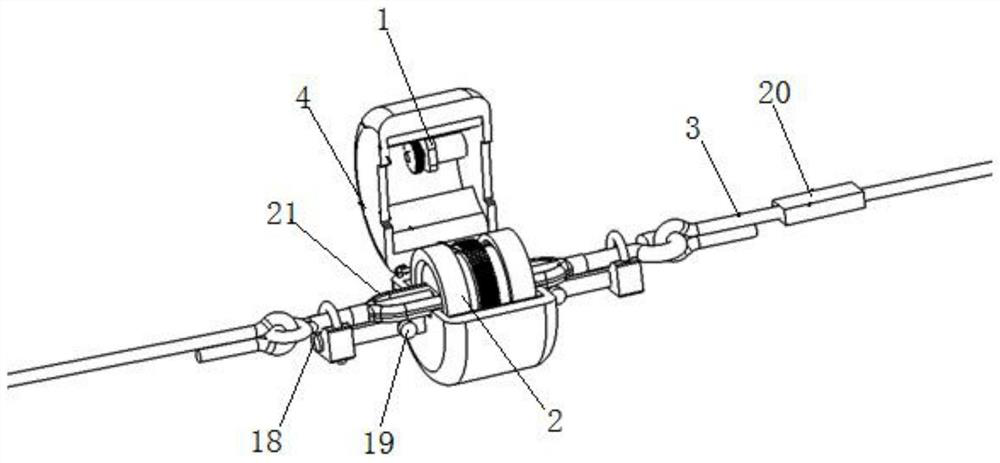
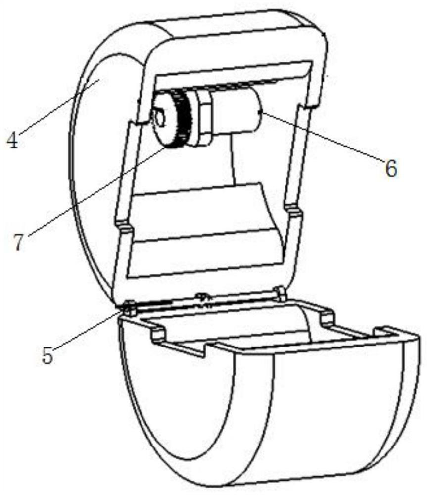
[0035] see Figure 1-4 , in the embodiment of the present invention: provide a kind of turnbuckle screw displacement tension automatic adjustment mechanism, comprise active driving mechanism 1, adjusting mechanism 2, steel wire rope 3, tension sensor 20 and turnbuckle screw 21; Active driving mechanism 1 is made up of drive motor 6 and active Composed of gear 7, driving motor 6 and driving gear 7 are installed in the active driving cover 4, and the rotating shaft of the driving motor 6 is fixedly connected with the driving gear 7; the active driving cover 4 is hinged as a whole by two semicircular shells through the connecting piece 5 , the adjustment mechanism 2 is assembled between the two semicircular shells.

[0036] Wherein, adjustment mechanism 2 is made up of anti-wear sleeve 10, tension adjustment sleeve 11, driven gear 12 and bearing 13; Bearings 13 are installed on the inner ring, and the outside of the anti-wear sleeve 10 is fitted and installed in the driving cove...

Embodiment 2

[0047] see Figure 5-6 , in the embodiment of the present invention: provide a kind of turnbuckle screw displacement tension automatic adjustment mechanism, comprise active driving mechanism 1, adjusting mechanism 2, steel wire rope 3, tension sensor 20 and turnbuckle screw 21; Active driving mechanism 1 is made up of drive motor 6 and active Composed of gear 7, driving motor 6 and driving gear 7 are installed in the active driving cover 4, and the rotating shaft of the driving motor 6 is fixedly connected with the driving gear 7; the active driving cover 4 is hinged as a whole by two semicircular shells through the connecting piece 5 , the adjustment mechanism 2 is assembled between the two semicircular shells.

[0048] Among them, it also includes the split bearing bush 14 arranged in the driving drive cover 4, and the split sliding bearing 15 matched with the split bearing bush 14, the split tension adjusting sleeve 16 and the split driven gear 17 , the split-type sliding ...


PUM


Abstract

The invention discloses an automatic adjustment mechanism for the displacement tension of a turnbuckle screw and its use method, which comprises an active driving mechanism, an adjusting mechanism, a steel wire rope, a tension sensor and a turnbuckle screw; the active driving mechanism is composed of a driving motor and a driving gear, and the adjusting The mechanism is composed of anti-wear sleeve, tension adjustment sleeve, driven gear and bearing; the invention transmits the power to the adjustment mechanism through the active drive mechanism, calculates the tension of the wire rope according to the motor current and the efficiency of the whole system, and rotates the flower through the adjustment mechanism. The turnbuckle in the middle of the turnbuckle screw is used to adjust the device. After the step of adjusting the tension of the wire rope is completed, the whole device can be removed from the turnbuckle screw, and the whole device will not remain on the wire rope. The disassembly and assembly are simple and convenient, and the adjustment of the tension of the wire rope is improved. Accuracy.

Description

technical field [0001] The invention relates to the technical field of construction engineering, in particular to an automatic adjustment mechanism for the displacement and pulling force of a turnbuckle screw and a method for using the same. Background technique [0002] In the construction of large-span cantilevered steel concrete structures, cantilevered steel trusses and other structures in construction projects, the method of tensioning the steel wire rope with turnbuckle screws is used to realize the displacement adjustment and position constraint of the structure. In the actual construction process, workers usually rely on pipe wrench or crowbar to adjust the turnbuckle screws to realize the tightness of the wire rope. The adjustment process is labor-intensive, the consistency of the wire rope tension is poor, the force is uneven, and there are hidden dangers of accidents. Contents of the invention [0003] The object of the present invention is to provide a turnbuck...

Claims


Application Information

Patent Timeline
Patent Type & Authority Patents(China)
IPC IPC(8): E04G21/18E04G21/12
CPCE04G21/18E04G21/1841E04G21/12E04G2021/128
Inventor 金仁才尹万云李志涛高文斌王鹏王鹏昌孔炯钱元弟房政
Owner CHINA MCC17 GRP
Why Eureka
Try Eureka