
Roller bit

A technology of roller cone bits and bits, which is applied to drill bits, earth-moving drilling, drilling equipment, etc., can solve the loosening of the connection between the claws of the three-cone bit and the bit seat, cannot guarantee the use effect of the bit, and reduce the rotation efficiency of the roller. and other problems, to achieve high rotation efficiency, improve wear resistance, and prevent loosening.

Active Publication Date: 2020-11-20
FOSHAN SHUNDE YUANJING MOLDING ELECTRIC CO LTD
View PDF5 Cites 0 Cited by
  • Summary
  • Abstract
  • Description
  • Claims
  • Application Information

AI Technical Summary

Problems solved by technology

[0003] However, there are still various problems in the use of various roller cone bits on the market, which have not solved the long-term rotation of the rotating bearing in the existing roller cone, which increases the frictional force and reduces the rotational efficiency of the roller cone. The connection between the claws of the roller cone bit and the bit seat is loose, which cannot be reinforced, and the use effect of the drill bit cannot be guaranteed. For this reason, we propose a roller cone bit

Method used


Image

  • Roller bit
  • Roller bit
  • Roller bit

Examples


Embodiment Construction

[0024] In order to make the technical means, creative features, goals and effects achieved by the present invention easy to understand, the present invention will be further elaborated below in conjunction with specific embodiments, but the following embodiments are only preferred embodiments of the present invention, not all. Based on the examples in the implementation manners, other examples obtained by those skilled in the art without making creative efforts all belong to the protection scope of the present invention. The experimental methods in the following examples, unless otherwise specified, are conventional methods, and the materials, reagents, etc. used in the following examples, unless otherwise specified, can be obtained from commercial sources.

[0025] Example:

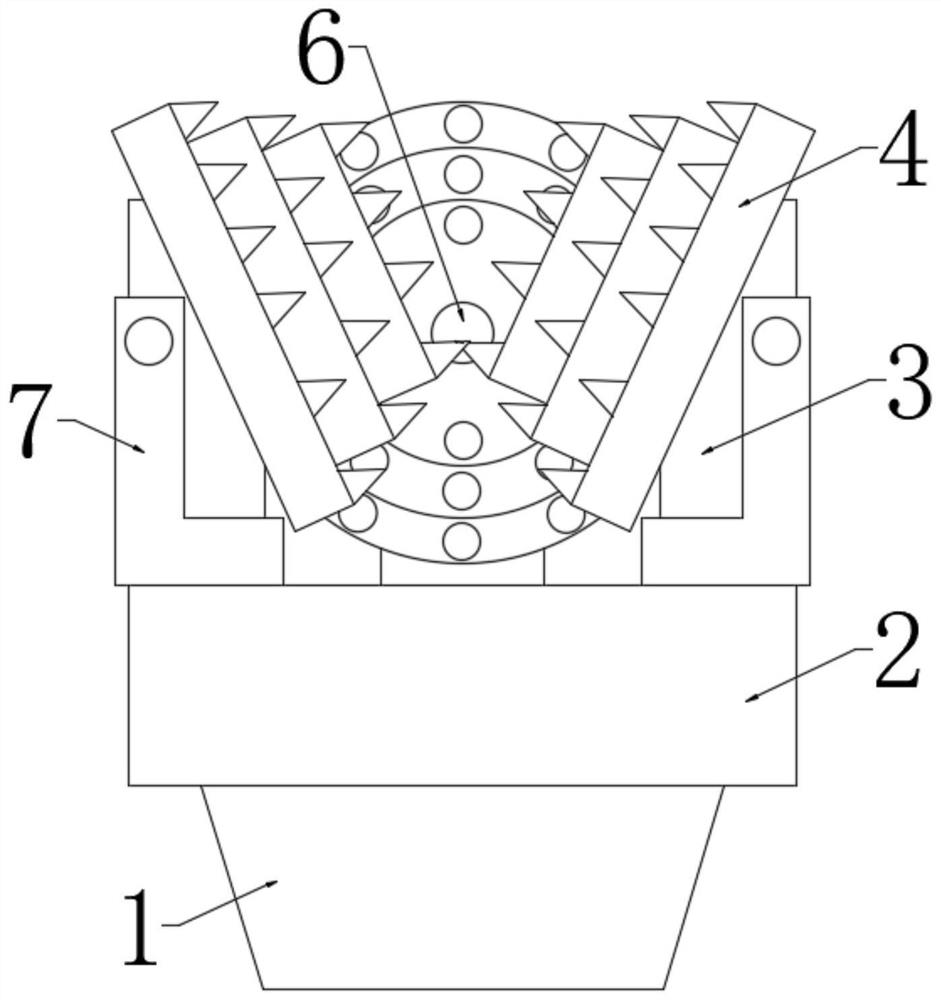
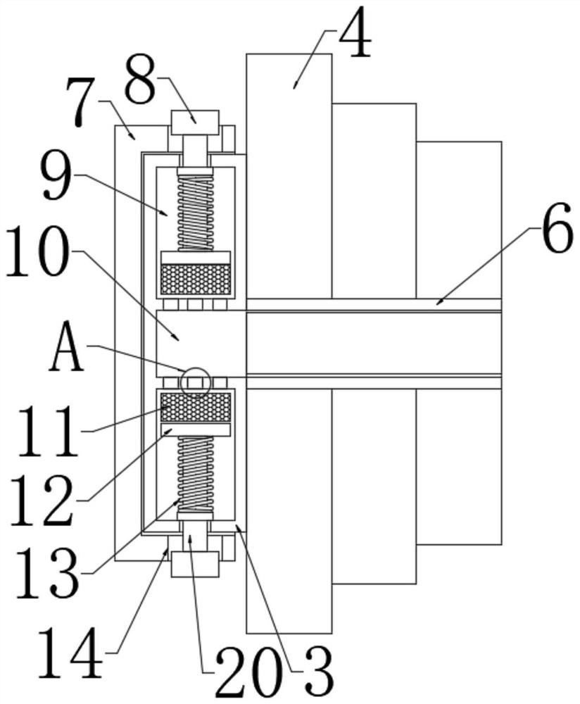
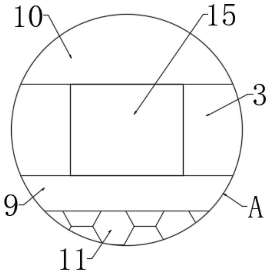
[0026] Such as Figure 1-Figure 3 Shown, a kind of roller cone bit, comprise drill base 2, cone 4, the junction of drill base 2 and cone 4 is provided with three-cone bit claw 3, the connection of cone ...


PUM


Abstract

The invention discloses a roller bit. The roller bit comprises a drill bit seat and a cone, a tricone bit jaw is arranged at the joint of the roller seat and the cone; a rotating bearing is arranged at the joint of the cone and the tricone bit jaw; a fixed seat is arranged on the surface of the outer side of the tricone bit jaw; extrusion rods penetrate through the surfaces of the two ends of thetricone bit jaw. First containing grooves are symmetrically formed in the tricone bit jaw. One end of the extrusion rod extends into the first containing groove; an extrusion plate is arranged on thesurface of the end, located in the first containing groove, of the extrusion rod. A sponge block is arranged on one side of the extrusion plate; a containing cavity is formed in the position, locatedon one side of the first containing groove, of the interior of the tricone bit jaw. A liquid outlet hole is formed in the tricone bit jaw and communicates with the containing cavity and the first containing groove, a spring sleeve is arranged at the joint of the extrusion rod and the first containing groove, and an extrusion block is arranged on the surface of the end, located outside the triconebit jaw, of the extrusion rod.

Description

technical field [0001] The invention relates to the technical field of drill bits, in particular to a roller cone bit. Background technique [0002] The roller cone bit is the most widely used type of drilling bit. When the roller cone bit is working, the cutting teeth alternately contact the bottom of the well, the rock-breaking torque is small, the contact area between the cutting teeth and the bottom of the well is small, the specific pressure is high, and it is easy to penetrate into the formation; the total length of the working blade is large, so the wear is relatively reduced. Roller cone bits can adapt to a variety of formations from soft to hard. [0003] However, there are still various problems in the use of various roller cone bits on the market, which have not solved the long-term rotation of the rotating bearing in the existing roller cone, which increases the frictional force and reduces the rotational efficiency of the roller cone. The connection between th...

Claims


Application Information

Patent Timeline
Patent Type & Authority Applications(China)
IPC IPC(8): E21B10/24E21B10/50
CPCE21B10/24E21B10/50
Inventor 章松
Owner FOSHAN SHUNDE YUANJING MOLDING ELECTRIC CO LTD
Learn More