
Lamp and lamp support thereof

A technology for lamp brackets and lamps, which is applied to the damage prevention measures of lighting devices, lighting and heating equipment, and semiconductor devices for light-emitting elements, etc. And other problems, to improve the power supply effect, reduce the service life, expand the effect of lighting range

Inactive Publication Date: 2020-11-20
杭州相辰科技有限公司
View PDF0 Cites 2 Cited by
  • Summary
  • Abstract
  • Description
  • Claims
  • Application Information

AI Technical Summary

Problems solved by technology

[0005] Although the above-mentioned patent can realize the maintenance of the lamps and lanterns of the high pole lamp; but when the lamps installed on the existing high pole are used on the port or the wharf, most of the lamps installed on the high pole are fixed and installed by the lamp bracket, and The lamp bracket is exposed outside, and it is difficult to adjust the irradiation range of multiple lamps when the lamp bracket is in a fixed state, which will affect the irradiation range of lamps installed on the high pole; at the same time, the exposed lamp bracket is prone to rust or breakage, which will affect The service life of the lamp bracket

Method used


Image

  • Lamp and lamp support thereof
  • Lamp and lamp support thereof
  • Lamp and lamp support thereof

Examples


Embodiment approach

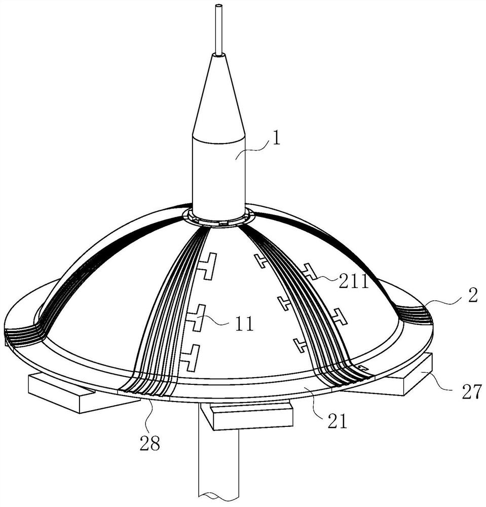
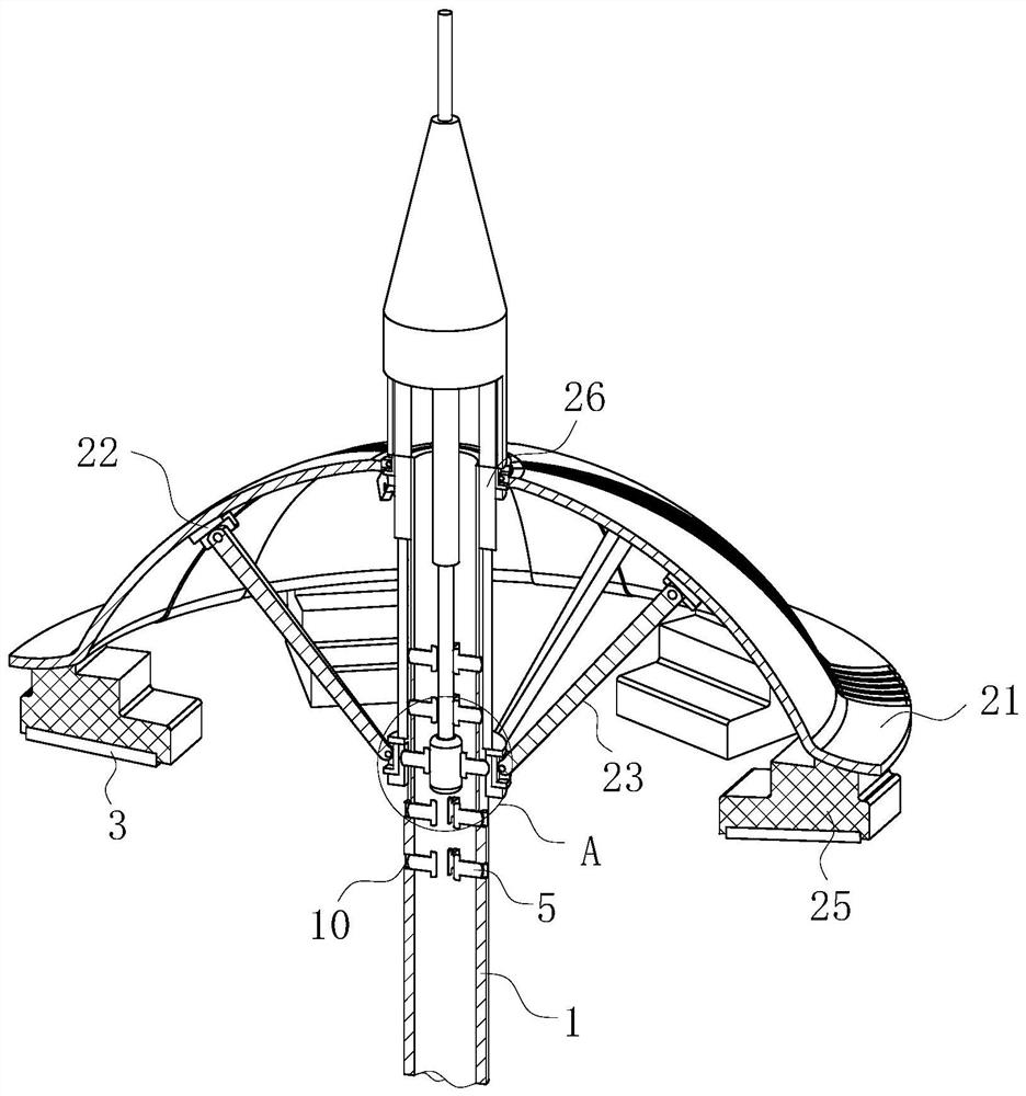
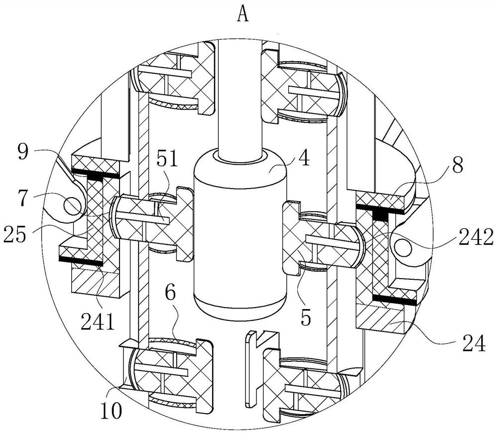
[0026] As an embodiment of the present invention, the outer wall of the support rod 1 is evenly provided with a plurality of insertion holes 10 in the vertical direction; the inner wall of the sliding ring 24 is evenly provided with insertion grooves 242, and The connecting groove 242 is slidably aligned with the insertion hole 10; an electric telescopic rod 26 is fixed inside the support high rod 1, and the telescopic end of the electric telescopic rod 26 is fixed with an extrusion column 4; a plurality of the insertion holes 10 A limit insert block 5 is provided inside, and a plurality of limit insert blocks 5 are all slidably mounted to the inner wall of the supporting high rod 1 through an elastic member; the inner ends of the plurality of limit insert blocks 5 and the extrusion column 4 The outer wall is pressed into contact, and the outer ends of a plurality of limit inserts 5 are slidably inserted into the inserting groove 242; the upper and lower ends of the extrusion co...


PUM


Abstract

The invention belongs to the field of lighting appliances, and particularly relates to a lamp and a lamp support thereof. The lamp support comprises a supporting high rod and a mounting bracket; the mounting bracket for mounting a lamp is arranged on the supporting high rod; the top ends of multiple fan-shaped arc plates are hinged to a fixing ring at the top end of the supporting high rod throughhinge blocks; hinge seats are arranged on the inner walls of the plurality of fan-shaped arc plates, and supporting rods are hinged in the plurality of hinge seats through hinge columns; the outer wall of the supporting high rod is slidably sleeved with sliding rings, mounting clamping blocks are arranged on the sliding rings, and the side walls of the multiple mounting clamping blocks are connected with the multiple supporting rods; electric telescopic rods are fixed to the two sides of the outer wall of the supporting high rod, and the telescopic ends of the electric telescopic rods are connected to the sliding rings; and lamp mounting discs are mounted on the bottom end faces of the multiple fan-shaped arc plates, and lamp bodies are mounted in the lamp mounting discs. The lighting ranges of the lamp bodies can be synchronously expanded, and the lighting ranges of the lamp bodies can be accurately and safely adjusted through the lamp support.

Description

Technical field [0001] The invention belongs to the field of lighting appliances, in particular to a lamp and its bracket. Background technique [0002] With the wider application range of lamps and lanterns nowadays, many new requirements have been put forward for lamps and lanterns. In many cases, lamps are fixed by lamp brackets. [0003] The high pole lamp generally refers to a new type of lighting device composed of a steel cone lamp pole above 15 meters and a high-power combined lamp structure. It consists of lamp holder, internal lamp electrical, lamp bracket and basic parts. The shape of the lamp holder can be determined according to user requirements, surrounding environment, and lighting needs. The internal lamps are mostly composed of floodlights and floodlights. The light source uses high-pressure sodium lamps with a lighting radius of 60 meters. [0004] The Chinese patent discloses a high pole lamp structure, the patent application number is 2017111395037, which incl...

Claims


Application Information

Patent Timeline
Patent Type & Authority Applications(China)
IPC IPC(8): F21S9/03F21V21/14F21V21/15F21V15/00F21V31/00F21Y115/10
CPCF21S9/035F21V15/00F21V21/14F21V21/15F21V31/00F21Y2115/10
Inventor 朱颖王玉婷
Owner 杭州相辰科技有限公司
Learn More