Wideband radiating elements including parasitic elements and related base station antennas

A technology of radiating elements and parasitic elements, which is applied to antenna unit combinations and antennas with different radiating element structures and polarization directions, and can solve problems such as difficulty in meeting performance specifications, difficulty in meeting performance specifications, and difficulty in ensuring performance.

Pending Publication Date: 2020-11-20
COMMSCOPE TECH LLC
View PDF7 Cites 2 Cited by
  • Summary
  • Abstract
  • Description
  • Claims
  • Application Information

AI Technical Summary

Problems solved by technology

Unfortunately, meeting performance specifications can be more difficult when broadband radiating elements are used because ensuring performance over a larger frequency range can be difficult,

Method used


Image

  • Wideband radiating elements including parasitic elements and related base station antennas
  • Wideband radiating elements including parasitic elements and related base station antennas
  • Wideband radiating elements including parasitic elements and related base station antennas

Examples


Embodiment Construction

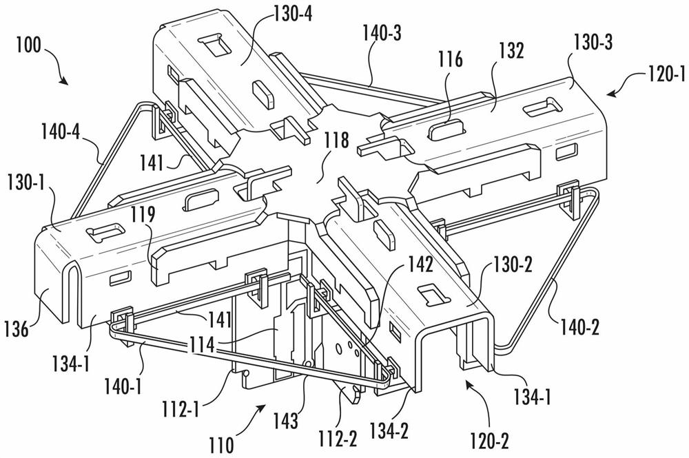
[0046] According to an embodiment of the present invention, there is provided a crossed-dipole radiating element comprising a parasitic element extending the frequency band of operation of the radiating element. These parasitic elements may be disposed between adjacent dipole arms of the radiating element and may couple RF energy from a dipole arm having a first polarization to a dipole arm having a second polarization. The parasitic elements increase the length of the current path and thus the effective length of the dipole arms. The parasitic element can be designed such that RF energy in a particular frequency range is preferentially coupled to the parasitic element, and thus the parasitic element can be used to primarily increase the effective length of the dipole arm for the selected frequency range, and provide little Or no increase in the effective length of the dipole arms for other frequency ranges is provided. Due to this design, relatively small dipole radiators ca...


PUM


Abstract

The invention relates to wideband radiating elements including parasitic elements and related base station antennas. A radiating element for a base station antenna includes a first dipole radiator that has a first dipole arm that has a front surface and first and second extensions that project rearward from respective side edges of the front surface of the first dipole arm; a second dipole radiator that has a second dipole arm that has a front surface and first and second extensions that project rearward from respective side edges of the front surface of the second dipole arm; and a parasiticelement having a first conductive segment that is configured to capacitively couple to the first extension of the first dipole arm, a second conductive segment that is configured to capacitively couple to the second extension of the second dipole arm, and a third conductive segment that electrically connects the first conductive segment to the second conductive segment.

Description

technical field [0001] The present invention relates generally to radio communications, and more particularly to base station antennas for cellular communications systems. Background technique [0002] Cellular communication systems are well known in the art. In a typical cellular communication system, a geographic area is divided into a series of regions, called "cells," which are served by corresponding base stations. Each base station may include baseband equipment, radios, and a base station antenna configured to provide two-way radio frequency ("RF") communications to fixed and mobile subscribers within the cell served by the base station. In many cases, each cell is divided into "sectors". In one common configuration, a hexagonal cell is divided into three 120° sectors in the azimuth plane, and each sector consists of one or more A base station antenna provides service. The antennas are often mounted on towers with the radiation beams ("antenna beams") generated by...

Claims


Application Information

Patent Timeline
IPC IPC(8): H01Q1/24H01Q1/36H01Q1/50H01Q19/10
CPCH01Q1/36H01Q1/50H01Q1/246H01Q19/10H01Q21/062H01Q19/108H01Q21/24H01Q5/42H01Q5/385H01Q1/1228
Inventor 李昀喆李曰民P·彼斯勒斯
Owner COMMSCOPE TECH LLC
Why Eureka
Try Eureka