Method for solving optimal energy flow of multi-energy-flow system, storage medium and equipment

A multi-energy flow, optimal technology, applied in the direction of system integration technology, information technology support system, AC network circuit, etc., can solve the problem of not considering the impact of transmission congestion on node energy price, etc.

Active Publication Date: 2020-11-20
NARI TECH CO LTD +4
View PDF2 Cites 0 Cited by
  • Summary
  • Abstract
  • Description
  • Claims
  • Application Information

AI Technical Summary

Problems solved by technology

The current technology mainly considers the electric-thermal coupling system or the electric coupling system. There are few research results on the node energy price of the

Method used


Image

  • Method for solving optimal energy flow of multi-energy-flow system, storage medium and equipment
  • Method for solving optimal energy flow of multi-energy-flow system, storage medium and equipment
  • Method for solving optimal energy flow of multi-energy-flow system, storage medium and equipment

Examples


Embodiment Construction

[0065] In order to better understand the essence of the present invention, the present invention will be further described below in conjunction with specific embodiments and accompanying drawings.

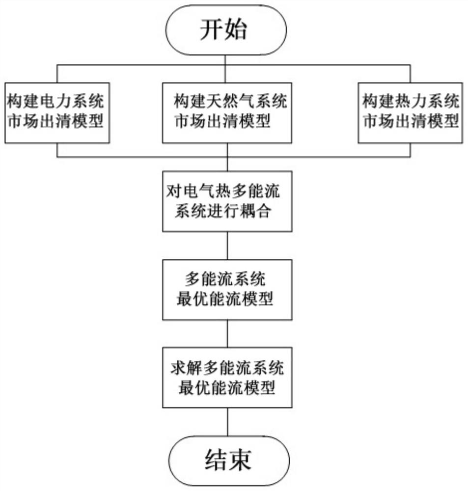
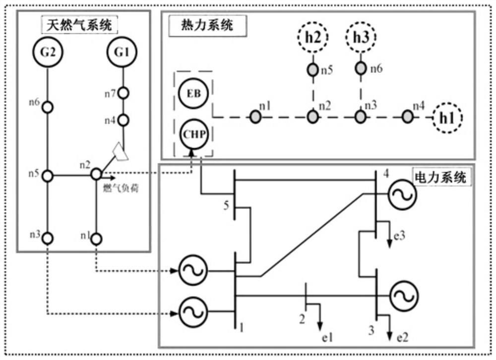
[0066] The embodiment of the present invention provides a method for solving the optimal energy flow of a multi-energy flow system, such as figure 1 shown, including the following steps:

[0067] Step 1. Establish the market-clearing model of the electric power system, the market-clearing model of the natural gas system and the market-clearing model of the thermal power system respectively.

[0068] 1. Establish a market clearing model for the power system.

[0069] In the power system market clearing model, rational power producers will strive to reduce costs, so the objective function is to minimize the total operating cost of the power system. The constraints of the power system market clearing model are the operation constraints of the power system, including power system nod...


PUM


Abstract

The invention discloses a method for solving optimal energy flow of a multi-energy-flow system. The method comprises the following steps: obtaining output cost data in the multi-energy-flow system andoperation cost data of each generator set; solving the output cost data and the operation cost data by adopting a pre-established multi-energy-flow system optimal energy flow model; and obtaining theoptimal energy flow of the multi-energy-flow system, wherein the input of the optimal energy flow model of the multi-energy-flow system is a cost coefficient of each generator set and an operation constraint condition of the multi-energy-flow system, and the output is the total cost of the multi-energy-flow system and a power generation capacity and a heat generation capacity of each generator set. Economic optimization operation among multiple energy systems such as electricity, gas, heat and the like can be achieved.

Description

technical field [0001] The invention relates to a solution method, storage medium and equipment for an optimal energy flow of a multi-energy flow system, and belongs to the field of comprehensive energy optimization. Background technique [0002] In the field of energy, various energy resources, such as electricity, natural gas, heat, etc., are planned and operated independently. This mode of operation is inefficient and has high operating costs. Therefore, breaking the original independent operation mode of each energy supply system and realizing the coordinated and optimized operation of various energy resources such as electricity, gas, and heat is an inevitable trend in the development of the future social energy supply system. In the context of the upcoming new generation of energy systems, conducting research on the joint planning of power systems, natural gas systems, and thermal systems with the power grid as the core will provide an important theoretical basis for ...

Claims


Application Information

Patent Timeline
IPC IPC(8): H02J3/00H02J3/46G06Q10/04G06Q50/06G06F30/20
CPCH02J3/00H02J3/466G06Q10/04G06Q50/06G06F30/20H02J2203/20H02J2300/40Y04S10/50Y02E40/70
Inventor 杨冬梅杨志宏孙勇李宝聚张筱辰陈永华杜炜刘刚何国鑫
Owner NARI TECH CO LTD
Why Eureka
Try Eureka