
Communication control method and device and electronic equipment

A communication control and modulation order technology, applied in wireless communication, electrical components, sustainable communication technology, etc., can solve problems such as dragging data transmission, high link power consumption, abnormal heating of equipment, etc.

Active Publication Date: 2020-11-20
GREE ELECTRIC APPLIANCES INC
View PDF5 Cites 2 Cited by
  • Summary
  • Abstract
  • Description
  • Claims
  • Application Information

AI Technical Summary

Problems solved by technology

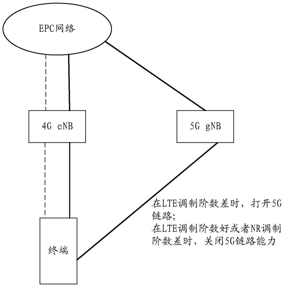
[0002] In related technologies, there are two current networking schemes: independent networking and non-independent networking. In terms of non-independent networking, the current network networking scheme generally uses a lower-level network to assist in completing high-level networking. In order to quickly realize the demand for large bandwidth and high speed, however, there are many disadvantages in the current non-independent networking: the first disadvantage is that the link power consumption of high-level networks (for example, 5G networks) is relatively large, that is, when high-level networks are not required The high-level networking method is used in some scenarios, which will greatly increase the power consumption of the network and make the equipment abnormally hot. Although many terminal manufacturers have added solutions to judge network power consumption, they cannot reduce the excessive power consumption caused by high-level networks. Problem; The second disadvantage is that the high-level networking method may hinder data transmission at the weak point of coverage, and some network NR (New Radio) edge areas, because the connection is in the edge area, the modulation order is low, and adding NR connections will increase the data card. pause
[0003] For the above problems, no effective solution has been proposed

Method used


Image

  • Communication control method and device and electronic equipment
  • Communication control method and device and electronic equipment
  • Communication control method and device and electronic equipment

Examples


Embodiment Construction

[0028] In order to enable those skilled in the art to better understand the solutions of the present invention, the following will clearly and completely describe the technical solutions in the embodiments of the present invention in conjunction with the drawings in the embodiments of the present invention. Obviously, the described embodiments are only It is an embodiment of a part of the present invention, but not all embodiments. Based on the embodiments of the present invention, all other embodiments obtained by persons of ordinary skill in the art without making creative efforts shall fall within the protection scope of the present invention.

[0029] It should be noted that the terms "first" and "second" in the description and claims of the present invention and the above drawings are used to distinguish similar objects, but not necessarily used to describe a specific sequence or sequence. It is to be understood that the data so used are interchangeable under appropriate ...


PUM


Abstract

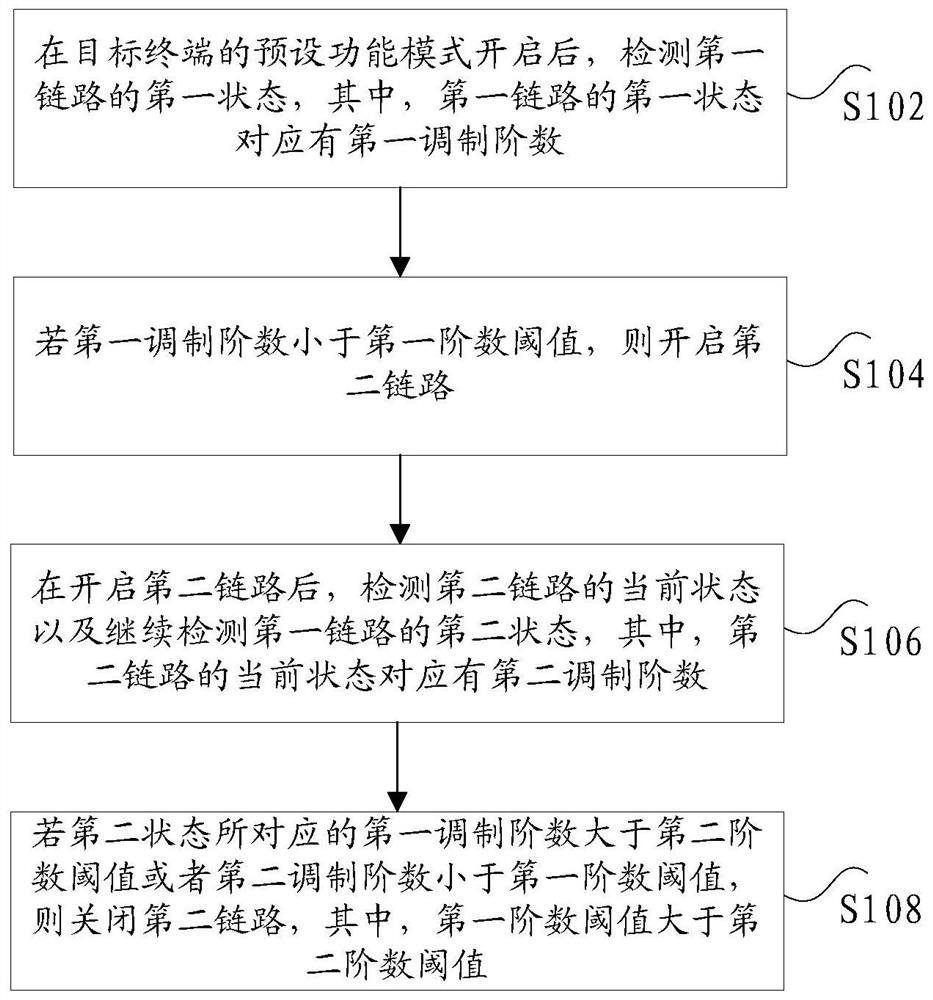
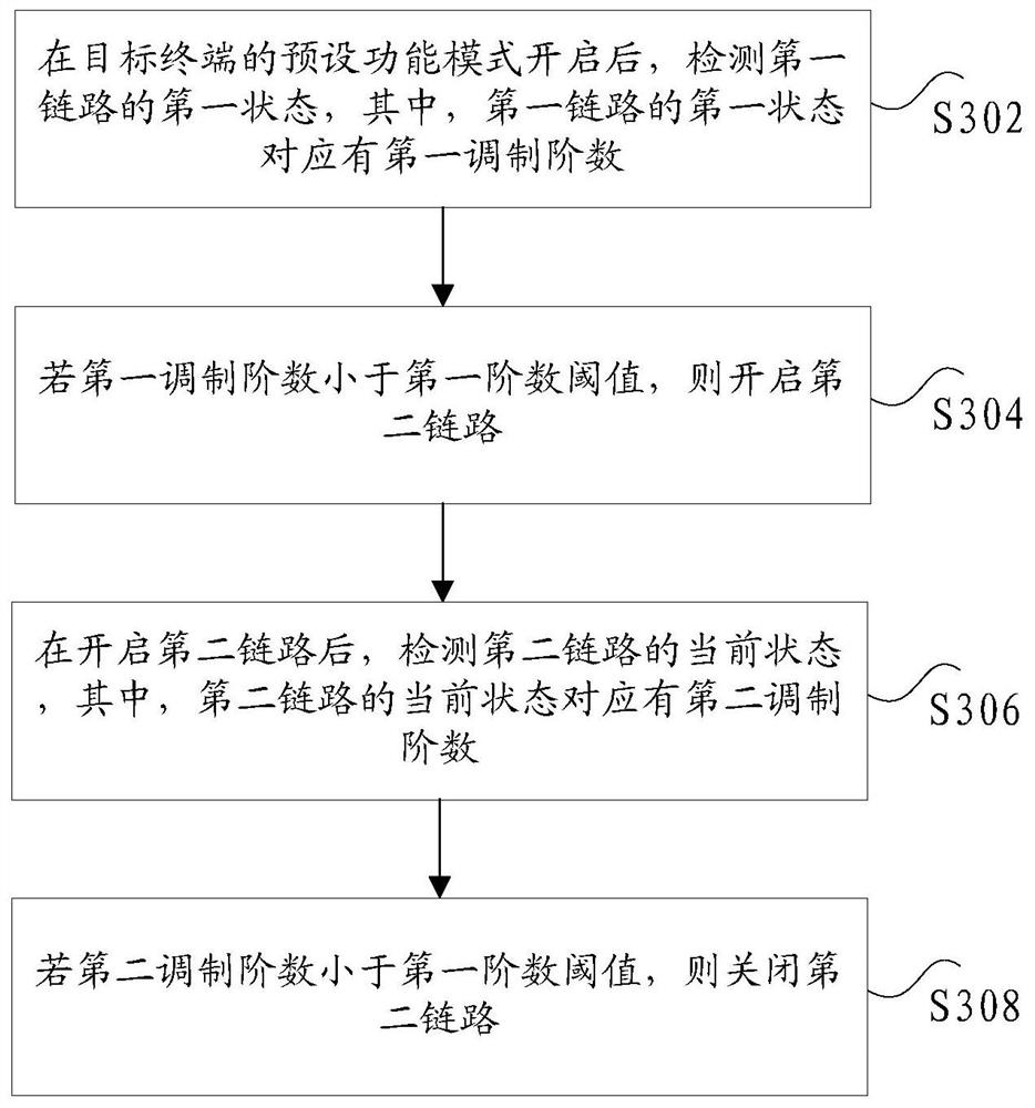
The invention discloses a communication control method and device and electronic equipment. The method comprises the steps that after a preset function mode of a target terminal is started, detectingthe first state of a first link, wherein the first state of the first link corresponds to a first modulation order; if the first modulation order is less than a first order threshold, opening a secondlink; after the second link is started, detecting the current state of the second link, continuously detecting the second state of the first link, wherein the current state of the second link corresponds to a second modulation order; and if the first modulation order corresponding to the second state is greater than a second order threshold or the second modulation order is less than the first order threshold, closing the second link, the first order threshold being greater than the second order threshold. According to the method and the device, the technical problem of relatively high powerconsumption if the dual-link connection of the terminal is always kept during modulation of the communication link in related technologies is solved.

Description

technical field [0001] The present invention relates to the technical field of communication control, in particular, to a communication control method and device, and electronic equipment. Background technique [0002] In related technologies, there are two current networking schemes: independent networking and non-independent networking. In terms of non-independent networking, the current network networking scheme generally uses a lower-level network to assist in completing high-level networking. In order to quickly realize the demand for large bandwidth and high speed, however, there are many disadvantages in the current non-independent networking: the first disadvantage is that the link power consumption of high-level networks (for example, 5G networks) is relatively large, that is, when high-level networks are not required The high-level networking method is used in some scenarios, which will greatly increase the power consumption of the network and make the equipment ab...

Claims


Application Information

Patent Timeline
Patent Type & Authority Applications(China)
IPC IPC(8): H04W52/02H04W76/15H04W76/34
CPCH04W52/0261H04W76/15H04W76/34Y02D30/70
Inventor 温波
Owner GREE ELECTRIC APPLIANCES INC
Learn More