
Bulb tube locking mechanism and ball tube lifting device
A locking mechanism and lifting device technology, which is applied in the field of medical equipment, can solve the problems of inaccurate locking positioning, difficult start and stop, and loud noise, and achieve the effects of efficient and stable locking, simple and convenient operation, and improved accuracy
- Summary
- Abstract
- Description
- Claims
- Application Information
AI Technical Summary
Problems solved by technology
Method used
Image

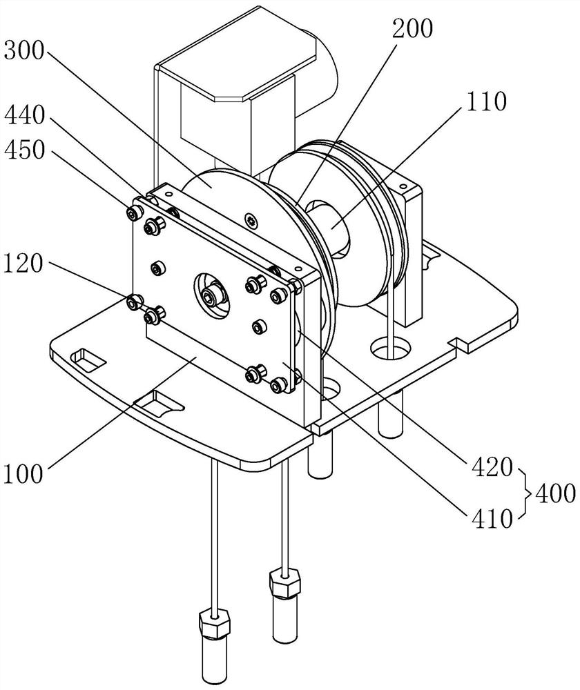
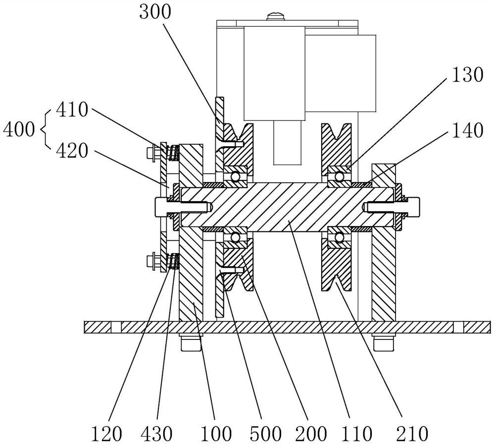
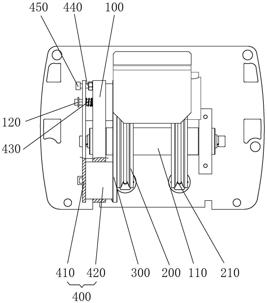
Examples
Embodiment Construction
[0023] Embodiments of the present invention are described in detail below, and examples of the embodiments are shown in the drawings, wherein the same or similar reference numerals denote the same or similar elements or elements having the same or similar functions throughout. The embodiments described below by referring to the figures are exemplary only for explaining the present invention and should not be construed as limiting the present invention.
[0024] In describing the present invention, it is to be understood that the terms "upper", "lower", "front", "rear", "left", "right", "transverse", "longitudinal", "vertical" etc. The indicated orientation or positional relationship is based on the orientation or positional relationship shown in the drawings, and is only for the convenience of describing the present invention and simplifying the description, rather than indicating or implying that the referred device or element must have a specific orientation, or in a specific...
PUM
 Abstract
Description
Claims
Application Information