Supercharge Your Innovation With Domain-Expert AI Agents!

Horizontal double-head vertical moving type milling device

A technology of vertical movement and milling device, applied in the field of mechanical processing, can solve the problems of torque consumption, unbalanced milling cutter seat, and uneven grinding, so as to reduce torque consumption, increase distribution range, and reduce vibration torque. The effect of consumption

Active Publication Date: 2020-11-24
黄朋飞
View PDF6 Cites 0 Cited by
  • Summary
  • Abstract
  • Description
  • Claims
  • Application Information

AI Technical Summary

Problems solved by technology

[0005] In this traditional installation method, there has always been a problem about dynamic balance. In the process of manual installation, there is a certain possibility that the milling cutter seat will be unbalanced. When the tool seat surface is unbalanced, The milling cutter will scratch the workpiece, and there may even be uneven grinding. In addition, when the spindle transmits the torque to the milling cutter seat, it may cause torque consumption. The formula T=9.55P / N (where T stands for torque, P stands for power, N stands for speed per minute), that is to say, under a certain power, the torque is inversely proportional to the speed, when the torque decreases, the speed will increase, which will cause If the speed is too fast, when the material of the workpiece is too hard, it will affect the service life of the tool. At the same time, the milling cutter will vibrate during milling. This milling vibration will affect the service life of the tool and the milling cutter bar

Method used


Image

  • Horizontal double-head vertical moving type milling device
  • Horizontal double-head vertical moving type milling device
  • Horizontal double-head vertical moving type milling device

Examples


Embodiment Construction

[0031] The following will clearly and completely describe the technical solutions in the embodiments of the present invention with reference to the accompanying drawings in the embodiments of the present invention. Obviously, the described embodiments are only some, not all, embodiments of the present invention. Based on the embodiments of the present invention, all other embodiments obtained by persons of ordinary skill in the art without making creative efforts belong to the protection scope of the present invention.

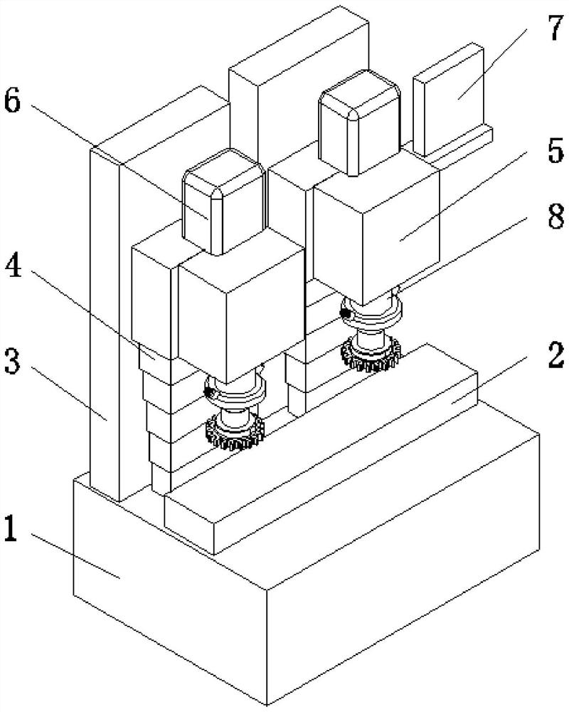
[0032] see Figure 2-9, a horizontal double-head vertically movable milling device, comprising a workbench 1, a workpiece placement table 2 is arranged in the middle of the upper surface of the workbench 1, and a rear support plate 3 is fixedly installed on one side of the upper surface of the workbench 1, and the rear support The front of the plate 3 is provided with a lifting platform 4, and the lifting platform 4 is fixedly installed on the upper surface of...


PUM


Abstract

The invention relates to the technical field of machining, and discloses a horizontal double-head vertical moving type milling device. The horizontal double-head vertical moving type milling device comprises a workbench, a middle part of an upper surface of the workbench is provided with a workpiece placing table, a back support plate is fixedly mounted at one side of the upper surface of the workbench, and a lifting platform is arranged in front of the back support table. The horizontal double-head vertical moving type milling device realizes a function of reducing vibration and reducing torque consumption through a vibration reduction device, and is provided with a spiral spring and a support rod at a bottom end of an optical axis for vibration reduction, wherein the spiral spring deforms back and forth on the support rod so as to absorb vibration frequency and gradually reduce the vibration frequency, additionally, a serpentine spring also can absorb the vibration frequency to reduce the vibration frequency, moreover, torque transferred by rotation of a main shaft is transferred to a half coupling of a front end, the half coupling transfers the torque through the serpentine spring to another half coupling, contact area between the serpentine spring and a U-shaped groove at outside of the half coupling is increased through rotation, consequently, the torque and friction forcedistribution range can be increased, and local torque consumption is reduced.

Description

technical field [0001] The invention relates to the technical field of mechanical processing, in particular to a horizontal double-head vertically movable milling device. Background technique [0002] In recent years, with the continuous development of the CNC lathe industry, the technology of using CNC lathes to process parts has become more and more mature. The milling device uses a rotating milling cutter to move on the workpiece to be processed. The rotating milling cutter can turn the surface of the workpiece The excess material is cut off, thereby grinding the workpiece into the desired shape. [0003] There are many types of milling cutters and milling machines for milling devices. In order to save efficiency and avoid wasting time when changing milling cutters, especially for some milling devices with relatively large milling heads, there are usually two milling heads, one One for rough milling and the other for finish milling to save time. [0004] Although the mi...

Claims


Application Information

Patent Timeline
Patent Type & Authority Applications(China)
IPC IPC(8): B23C1/08B23Q11/00
CPCB23C1/08B23Q11/0032
Inventor 黄朋飞
Owner 黄朋飞
Features
  • R&D
  • Intellectual Property
  • Life Sciences
  • Materials
  • Tech Scout
  • Unparalleled Data Quality
  • Higher Quality Content
  • 60% Fewer Hallucinations
Learn More