
Fixture for clamping magnets and operation method thereof

An operation method and fixture technology, applied in the direction of workpiece clamping devices, manufacturing tools, etc., can solve the problems of limited clamping shape and size, insufficient clamping force, lack of versatility, etc., and achieve universality and high clamping force , the effect of large adjustable range of movement

Inactive Publication Date: 2020-11-24
NORTHWESTERN POLYTECHNICAL UNIV
View PDF5 Cites 0 Cited by
  • Summary
  • Abstract
  • Description
  • Claims
  • Application Information

AI Technical Summary

Problems solved by technology

But at present, the clamps for clamping magnets are relatively rare, and there are limitations in clamping shape and size, insufficient clamping force, and lack of versatility.

Method used


Image

  • Fixture for clamping magnets and operation method thereof
  • Fixture for clamping magnets and operation method thereof
  • Fixture for clamping magnets and operation method thereof

Examples


Embodiment Construction

[0027] The present invention will be further described below in conjunction with the accompanying drawings and embodiments.

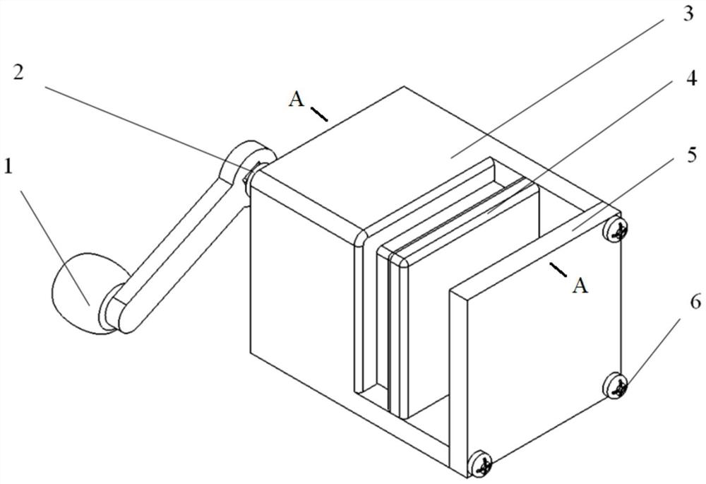
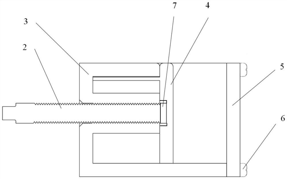
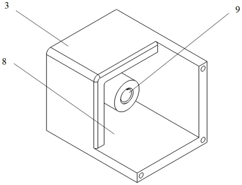
[0028] like Figure 1 to Figure 5 As shown, a clamp for clamping a magnet according to the present invention includes a handle 1, a transmission threaded rod 2, a clamp body 3, a moving clamp block 4 and a fixed clamp block 5;

[0029] The function of the clamp main body 3 is to support and fix, and a through hole 9 is provided in the middle position; the transmission threaded rod 2 passes through the through hole 9, one end is connected with the movable clamp block 4, and the other end passes through the left side of the clamp main body 3. connected with the handle 1; the fixed clamp block 5 is fixedly connected with the clamp main body 3 on the right side of the clamp main body 3;

[0030] The magnet is placed between the movable clamping block 4 and the fixed clamping block 5, and turning the handle 1 can make the movable clamping block 4 move left ...


PUM


Abstract

The invention discloses a fixture for clamping magnets. The fixture includes a handle, a transmission threaded rod, a fixture main body, a moving clamping block and a fixing clamping block. A throughhole is formed in the middle of the fixture main body, the transmission threaded rod penetrates through the through hole, one end of the transmission threaded rod is connected with the moving clampingblock, the other end of the transmission threaded rod penetrates out of the left side of the fixture main body to be connected with the handle, the fixing clamping block is located on the right sideof the fixture main body and fixedly connected with the fixture main body, the magnets are placed between the moving clamping block and the fixing clamping block, and the handle is rotated to make themoving clamping block move left and right, so that the magnets can be clamped and fixed. According to the fixture, the distance between the moving clamping block and the fixing clamping block can beadjusted through the rotation of the handle, the operation is safe and simple, the self-locking can be achieved, and the problem that the magnets can not be clamped conveniently can be effectively solved. The adjustable range of the clamping blocks of the fixture is large, the clamping force is high, the reliable clamping of the magnets with different size can be achieved, and the universality canbe achieved.

Description

technical field [0001] The invention belongs to the field of mechanical processing, and in particular relates to a fixture and an operating method thereof. Background technique [0002] Fixture refers to the device used to fix the processing object in the process of mechanical manufacturing so that it can occupy the correct position to accept construction or inspection, also known as fixture. In a broad sense, any process in the process, the device used to install the workpiece quickly, conveniently and safely, can be called a fixture. [0003] The application of magnets is very extensive, and has been widely used in various fields such as electronics, electricity, machinery, transportation, and medical treatment. During the use of the magnet, it is often necessary to fix the magnet, and it is a good choice to fix the magnet with a clamp. However, at present, clamps for clamping magnets are relatively rare, and have the disadvantages of limited clamping shape and size, ins...

Claims


Application Information

Patent Timeline
Patent Type & Authority Applications(China)
IPC IPC(8): B25B11/00
CPCB25B11/00
Inventor 金春雨刘敏艳霍怡惠纵园王许泉罗明
Owner NORTHWESTERN POLYTECHNICAL UNIV
Learn More