Laser with calibration mechanism corresponding to axial degree of discharge tube

A calibration mechanism and corresponding technology, applied in the field of lasers, can solve problems such as poor practicability, achieve the effect of solving the poor efficiency of axial calibration, improving work efficiency, and improving installation efficiency

Pending Publication Date: 2021-03-26
湖南奕瀚电子科技有限公司
View PDF0 Cites 0 Cited by
  • Summary
  • Abstract
  • Description
  • Claims
  • Application Information

AI Technical Summary

Problems solved by technology

[0003] The purpose of the present invention is to solve the shortcomings of poor practicability in the prior art, and propose a laser with a calibration mechanism corresponding to the axis of the discharge tube

Method used


Image

  • Laser with calibration mechanism corresponding to axial degree of discharge tube
  • Laser with calibration mechanism corresponding to axial degree of discharge tube
  • Laser with calibration mechanism corresponding to axial degree of discharge tube

Examples


Embodiment 1

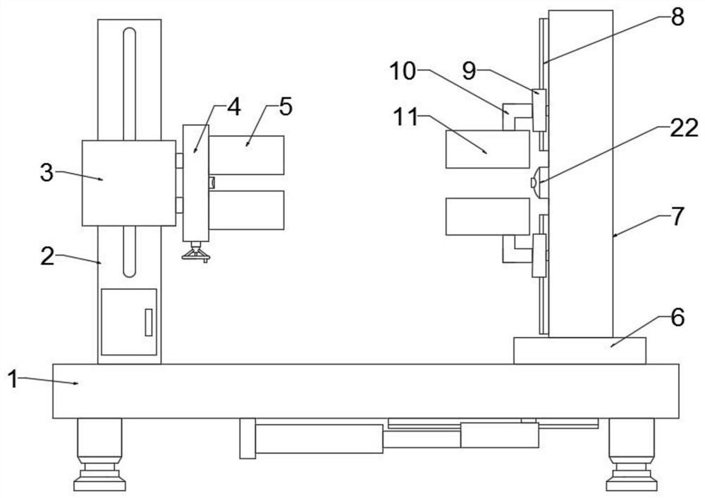
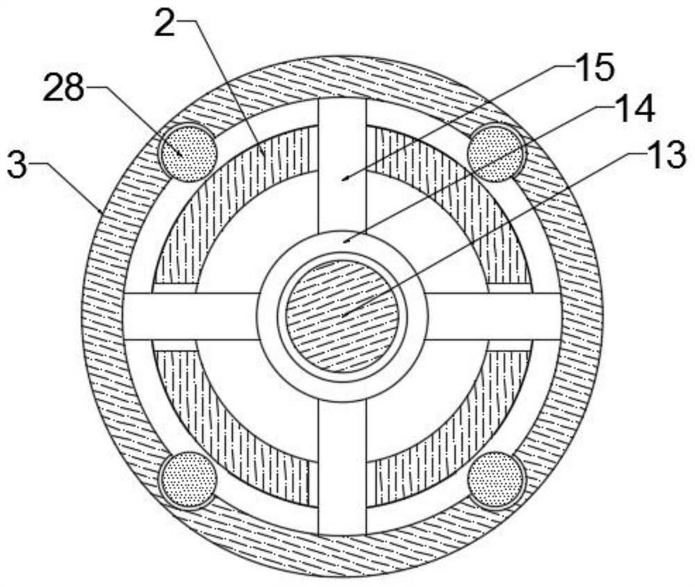
[0022] Embodiment 1: see Figure 1-4 , a laser with a calibration mechanism corresponding to the axis of the discharge tube in the present invention includes a base plate 1, which is a horizontally arranged rectangular plate, and one side of the top surface of the base plate 1 is vertically fixed with a cylindrical Guide column 2; the cylinder upper movable cover of guide column 2 is provided with stabilizing sleeve 3, and the tube body side of stabilizing sleeve 3 is vertically fixedly connected with disc 4, and the upper and lower ends of the inner surface of disc 4 are horizontally movable respectively. There is a movable splint 5 with an inner curved surface opposite to it; the other side of the top surface of the bottom plate 1 is horizontally provided with a rectangular sliding plate 6, and the middle part of the top surface of the sliding plate 6 is vertically fixed with a rectangular support column 7; the support column 7 The upper and lower parts of the inner surface ...

Embodiment 2

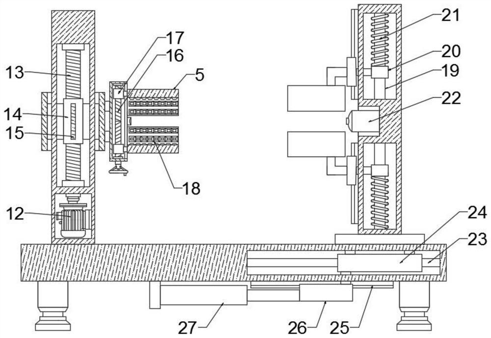
[0027] Embodiment 2: When the present invention is used, firstly, the motor 12 and the electric push cylinder 27 are electrically connected to the external power supply through wires respectively; It is convenient to place the laser of the discharge tube to be calibrated horizontally between the two fixed splints 11. Under the elastic action of the thrust spring 21, it is convenient to push the sleeve 20 to drive the sliding block 9 at the outer end of the connecting rod to slide on the T-shaped guide rail 8. Through the relative sliding of the sliding block 9, it is convenient to drive the fixed splint 11 at the bent end of the L-shaped curved rod 10 to clamp and fix the laser; the operator then places the discharge tube between the movable splints 5, and drives the rotating shaft by rotating the adjustment hand wheel 16 is rotated, the positive and negative threads on the surface of the rotating shaft 16 facilitate the relative movement of the two threaded pipes 17, and the r...


PUM


Abstract

The invention discloses a laser with a calibration mechanism corresponding to an axial degree of a discharge tube. The laser comprises a bottom plate, and one side of the top surface of the bottom plate is fixedly connected with a guide column; a stabilizing sleeve sleeves a column body of the guide column, a disc is fixedly connected to one side of a pipe body of the stabilizing sleeve, and clamping plates are transversely arranged at the upper end and the lower end of the inner side surface of the disc; T-shaped guide rails are fixedly connected to the upper portion and the lower portion ofthe inner side surface of the supporting column, and an L-shaped bent rod is transversely and fixedly connected to the inner side surface of each sliding block; the top of the bent end of each L-shaped bent rod is transversely and fixedly connected with a fixed clamping plate; a lifting cavity is formed in the upper portion in the guide column, and a correction mechanism is arranged in the liftingcavity; and a thrust assembly is arranged in each thrust cavity; According to the invention, operation is convenient, and through the thrust assembly and the adjusting assembly, the problem that theexisting discharge tube and the laser are inconvenient to clamp during axial degree calibration is solved; and through cooperative use of the correction mechanism and a stabilizing assembly, the problem that the existing laser axial degree calibration efficiency is poor is solved too.

Description

technical field [0001] The invention relates to the technical field of discharge tube axis calibration, in particular to a laser with a calibration mechanism corresponding to the discharge tube axis. Background technique [0002] Since the laser discharge tube is a special processing material, it cannot be processed by the commonly used cold processing method. At present, the processing method of thermoplastic deformation is used. This processing method is difficult to guarantee the dimensional accuracy of the discharge tube required by the laser, so the resonance of the laser cannot be guaranteed. The consistency of the nozzle of the discharge tube in the cavity affects the power of the laser; when calibrating the axis of the discharge tube in the laser resonator cavity, it is not convenient to quickly clamp and fix the laser and the discharge tube respectively; It is convenient to quickly calibrate according to the axis of the discharge tube, but it is not convenient to qu...

Claims


Application Information

Patent Timeline
Patent Type & Authority Applications(China)
IPC IPC(8): H01S3/03
CPCH01S3/03
Inventor 黄盼
Owner 湖南奕瀚电子科技有限公司
Why Eureka
Try Eureka