Shoe sole ejector for sneaker processing

A technology for sports shoes and strippers, which is applied in the field of strippers, can solve the problems of laboriousness and troublesome operation, and achieve the effect of convenient operation and stable movement.

Active Publication Date: 2020-11-24
永州加伟鞋材制品有限公司
View PDF6 Cites 0 Cited by
  • Summary
  • Abstract
  • Description
  • Claims
  • Application Information

AI Technical Summary

Problems solved by technology

[0005] In order to overcome the shortcomings of hooking one end of the sole once and then hooking the other end once to remove the sole, the operation is cumbersome, and a person needs to pick up the sole and throw it into the collection container, which is laborious. The technical problem is: provide a A kind of shoe sole stripper for sports shoes processing that can replace manual hooking out of the sole, is easy to operate, and does not require people to move the sole for collection.

Method used


Image

  • Shoe sole ejector for sneaker processing
  • Shoe sole ejector for sneaker processing
  • Shoe sole ejector for sneaker processing

Examples


Embodiment 1

[0025] refer to Figure 1-Figure 4 , a sole stripper for sports shoes processing, including a support base 1, a support plate 2, a placement frame 3, a cover plate 4, a mounting block 5, a guide rod 6, a movable frame 7, a driving mechanism 8 and a clamping mechanism 9 , both sides of the top of the support base 1 are fixedly connected with support plates 2, the tops of the support plates 2 on the front and rear sides are fixedly connected with a placement frame 3, and the right side of the top of the placement frame 3 is hinged with a cover plate 4, and the cover plate 4 is connected to the placement frame 3 Cooperate, the upper part of the right side of the front and rear sides outside the frame 3 is fixedly connected with the installation block 5, and the upper part of the left side of the installation block 5 is fixedly connected with two guide rods 6, and the sliding type between the four guide rods 6 is provided with movable parts. The frame 7 and the movable frame 7 are...

Embodiment 2

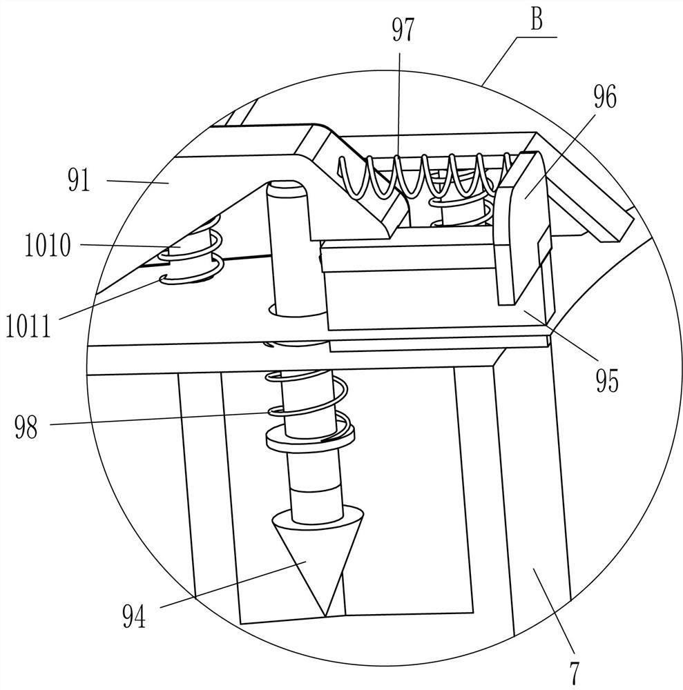
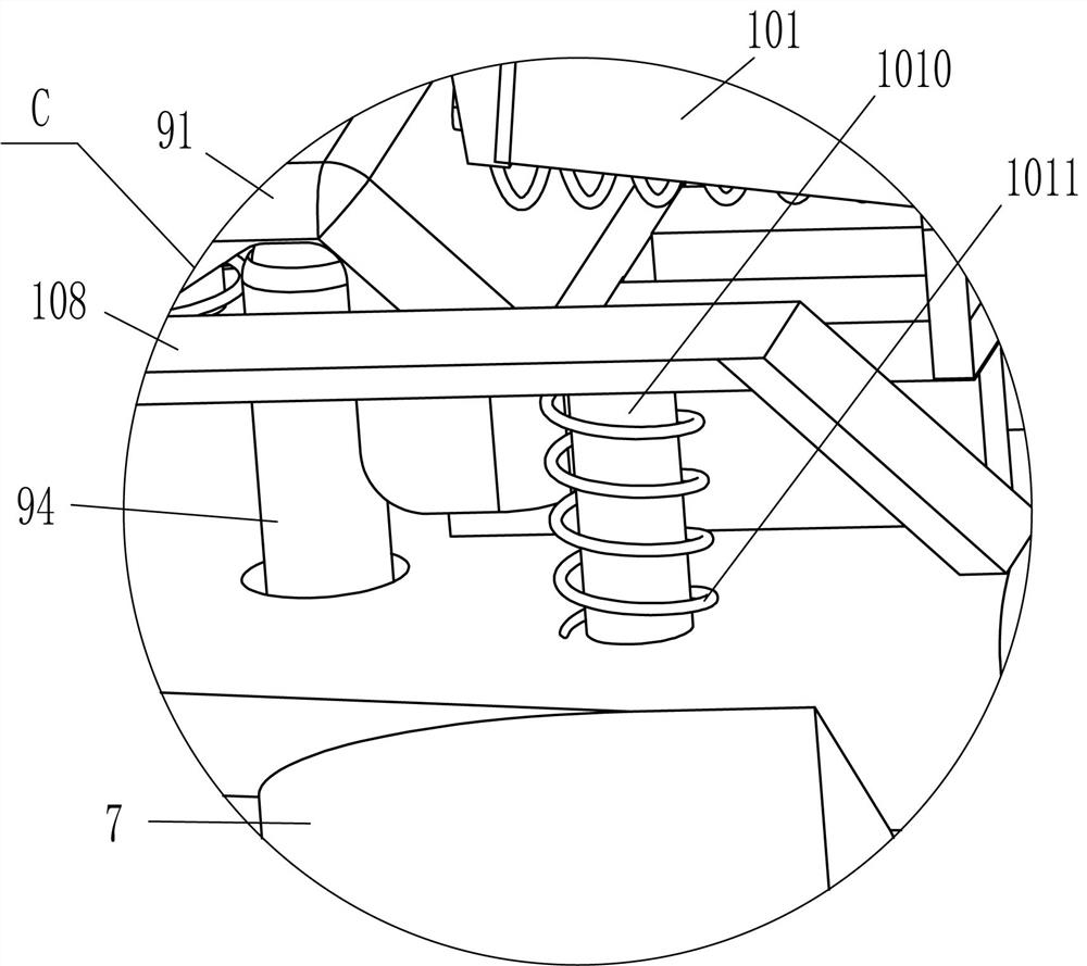
[0032] refer to figure 1 , figure 2 , Figure 4 and Figure 5 Compared with Embodiment 1, the main difference of this embodiment is that in this embodiment, a shoe pushing mechanism 10 is also included. , reel 106, push plate 107, contact plate 108, push shoe plate 109, slide bar 1010 and the 4th spring 1011, mounting block 5 tops are fixedly connected with mounting frame 101, between front and back both mounting frames 101 left ends A rotating rod 102 is connected to the rotating rod 102, and a torsion spring 104 is provided at the hinge of the rotating rod 102 and the mounting frame 101. The front and rear ends of the rotating rod 102 are fixedly connected with a swing rod 103, and the left end of the swing rod 103 is fixedly connected with a push plate 107, and the movable frame 7. Slide bars 1010 are slidably arranged in the middle and right parts of the front, rear, and front sides of the top, and contact plates 108 are fixedly connected between the tops of the two sl...

Embodiment 3

[0035] refer to figure 1 , figure 2 , image 3 and Figure 6 The main difference between this embodiment and embodiment 1 and embodiment 2 is that in this embodiment, a guide rod 11 and a guide sleeve 12 are also included. , the sliding type is provided with guide rod 11 in the guide sleeve 12, and the inner ends of the guide rods 11 at the front and rear sides are fixedly connected with the left parts of the front and rear sides of the transverse rack 93 respectively.

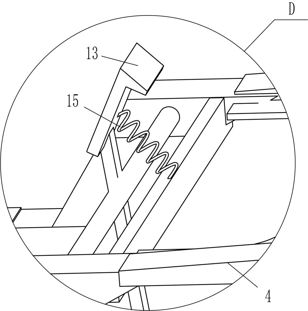
[0036] It also includes a clamping rod 13 and an elastic member 15. A clamping rod 13 is rotatably connected between the left part of the front and rear sides of the right part of the cover plate 4, and an elastic member 15 is connected between the upper right side of the clamping rod 13 and the top of the cover plate 4. , the middle part of the outer right side of the placement frame 3 has a clamping hole 14 that cooperates with the clamping rod 13 .

[0037] When the transverse rack 93 moves, the transv...


PUM


Abstract

The invention relates to an ejector, in particular to a shoe sole ejector for sneaker processing. The invention aims to solve the technical problem of how to design the shoe sole ejector for sneaker processing, wherein a shoe sole can be hooked out by replacing a manual operation, the shoe sole ejector is convenient to operate, it is not needed to collect the shoe sole as people move and the shoesole ejector is relatively labor-saving. The ejector comprises a supporting base, wherein supporting plates are symmetrically and fixedly connected to the top of the supporting base, and a placing frame is mounted between the end parts of the two supporting plates far away from the supporting base. By pulling a cover plate to open the shoe sole ejector, the right part is in contact with a first piston rod, so that the shoe sole ejector moves leftward and a movable frame moves rightward above the placing frame. A shoe clamping rod moves downward to be inserted into the shoe sole to clamp the shoe sole. After the cover plate is unloosened to close, the shoe clamping rod drives the shoe sole and a die to be separated and moved outside the placing frame, so that it is not needed to hook out the shoe sole from the die, and therefore, the shoe sole ejector is convenient to operate and relatively labor-saving.

Description

technical field [0001] The invention relates to a stripper, in particular to a sole stripper for sports shoes processing. Background technique [0002] Sports shoes are shoes designed and manufactured according to the characteristics of people participating in sports or traveling. The soles of sports shoes are different from ordinary leather shoes and rubber shoes. They are generally soft and elastic, and can play a certain role in cushioning. It can enhance elasticity during exercise, and some can prevent ankle injuries. Therefore, sports shoes are mostly worn when doing sports, especially for high-intensity physical sports, such as basketball, running, etc. In the processing of sports shoes, soles need to be made, because the soles of running shoes are formed by molds Yes, after the sole is formed, people need to take the sole out of the mold. [0003] At present, most of them are operated manually through a large number of manual operations. First, one needs to press t...

Claims


Application Information

Patent Timeline
Patent Type & Authority Applications(China)
IPC IPC(8): B29C33/44B29L31/50
CPCB29C33/44B29L2031/504
Inventor 贺佳林
Owner 永州加伟鞋材制品有限公司
Why Eureka
Try Eureka