Supercharge Your Innovation With Domain-Expert AI Agents!

Phase sequence detection method based on orthogonal area

A phase sequence detection, positive phase sequence technology, applied in the direction of phase sequence/synchronization indication, can solve the problems of increasing circuit hardware cost, occupying CPU resources, complex algorithms, etc., to reduce CPU power consumption, simplify hardware circuit, and reduce CPU consumption. The effect of resources

Active Publication Date: 2020-11-24
山东博奥斯能源科技有限公司
View PDF10 Cites 1 Cited by
  • Summary
  • Abstract
  • Description
  • Claims
  • Application Information

AI Technical Summary

Problems solved by technology

[0003]At present, there are two common three-phase phase sequence detection methods, one is realized by using a complex analog circuit plus a zero-crossing comparison circuit, using two of the three phases of the commercial power The zero-crossing point of the phase voltage is used to generate two pulse signals of the same frequency, which are sent to the digital processor for judgment processing. This detection method increases the cost of circuit hardware, its stability is poor, and the response speed is slow; the other is to detect any adjacent For two-phase voltage, the positive sequence and negative sequence vectors are calculated respectively through CLARK and PARK transformations, and the vector sum of the positive and negative sequences is used to distinguish the positive and negative phase sequences. The algorithm is complex and time-consuming. This method requires a lot of calculations and is very Occupies CPU resources, and at the same time, the phase-locking accuracy will be affected due to voltage waveform distortion, thus affecting the performance of the inverter

Method used


Image

  • Phase sequence detection method based on orthogonal area
  • Phase sequence detection method based on orthogonal area
  • Phase sequence detection method based on orthogonal area

Examples


Embodiment Construction

[0041] The following will clearly and completely describe the technical solutions in the embodiments of the present invention with reference to the accompanying drawings in the embodiments of the present invention. Obviously, the described embodiments are only some, not all, embodiments of the present invention. Based on the embodiments of the present invention, all other embodiments obtained by persons of ordinary skill in the art without making creative efforts belong to the protection scope of the present invention.

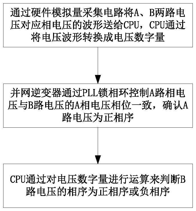
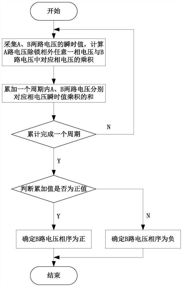
[0042] Such as figure 1 As shown, a phase sequence detection method based on the orthogonal area includes the following steps:

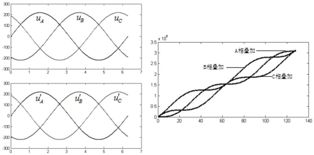
[0043] Step 1: Through the hardware analog quantity acquisition circuit of the main control board, the waveforms of the two three-phase AC voltages of A and B corresponding to the phase voltage are sent to the CPU through the CPU analog quantity acquisition interface, and the CPU transmits the voltage waveform through the internal A / ...


PUM


Abstract

The invention provides a phase sequence detection method based on an orthogonal area, and the method comprises the steps: 1, transmitting waveforms of phase voltages corresponding to an A-path voltageand a B-path voltage to a CPU through a hardware analog collection circuit, and enabling the CPU to convert the voltage waveforms into voltage digital values through an internal A / D conversion circuit; 2, controlling the A-phase voltage of the A-path voltage to be consistent with the A-phase voltage of the B-path voltage by the grid-connected inverter through a PLL (Phase Locked Loop), and determining that the phase sequence of the A path is a positive phase sequence; 3, the CPU judges whether the phase sequence of the B-path voltage is a positive phase sequence or a negative phase sequence by calculating the voltage digital quantity; the specific operation method comprises the steps that in one period, any phase voltage, except for phase locking, of the A-path voltage is multiplied by the instantaneous value of the corresponding phase voltage in the B-path voltage, accumulation is conducted, positive and negative judgment is conducted on the obtained accumulated value, and if the accumulated value is a positive value, it is indicated that the B-path voltage is a positive phase sequence; and if the accumulated value is a negative value, indicating that the B-path voltage is a negative phase sequence.

Description

technical field [0001] The invention relates to a phase sequence detection method based on an orthogonal area, and belongs to the technical field of phase sequence detection. Background technique [0002] Many electrical devices need to detect the phase sequence of the mains power when they are used. For example, the grid-connected inverter needs to judge the phase sequence of the grid before generating electricity, otherwise it will affect the normal operation of the inverter; in the field of automatic control, when A and B two When three-phase AC power supplies with the same frequency and amplitude are connected in parallel or switched, the first thing to do is to detect the phase sequence. [0003] At present, there are two common three-phase phase sequence detection methods. One is realized by using a complex analog circuit plus a zero-crossing comparison circuit, which uses the zero-crossing points of the two-phase voltages in the three-phase mains to generate two pulse...

Claims


Application Information

Patent Timeline
Patent Type & Authority Applications(China)
IPC IPC(8): G01R29/18
CPCG01R29/18
Inventor 耿传勇夏景柱
Owner 山东博奥斯能源科技有限公司
Features
  • R&D
  • Intellectual Property
  • Life Sciences
  • Materials
  • Tech Scout
  • Unparalleled Data Quality
  • Higher Quality Content
  • 60% Fewer Hallucinations
Learn More