Agricultural mechanical fertilizer applicator

A technology of agricultural machinery and fertilizer applicator, applied in the agricultural field, can solve the problem that the fertilizer cannot be applied to the inside of the groove, etc.

Active Publication Date: 2020-11-27
CHONGQING ACAD OF AGRI SCI
View PDF3 Cites 2 Cited by
  • Summary
  • Abstract
  • Description
  • Claims
  • Application Information

AI Technical Summary

Problems solved by technology

[0003] When the agricultural fertilizer applicator is fertilizing, the fertilizer is continuously discharged from the guide pipe downwards, and some of the fertilizers are so light that when the agricultural fertilizer applicator makes a quick turn on the land, the fertilizer will be thrown out , resulting in the situation that part of the thrown fertilizer cannot be carried out inside the trench

Method used


Image

  • Agricultural mechanical fertilizer applicator
  • Agricultural mechanical fertilizer applicator
  • Agricultural mechanical fertilizer applicator

Examples


Embodiment 1

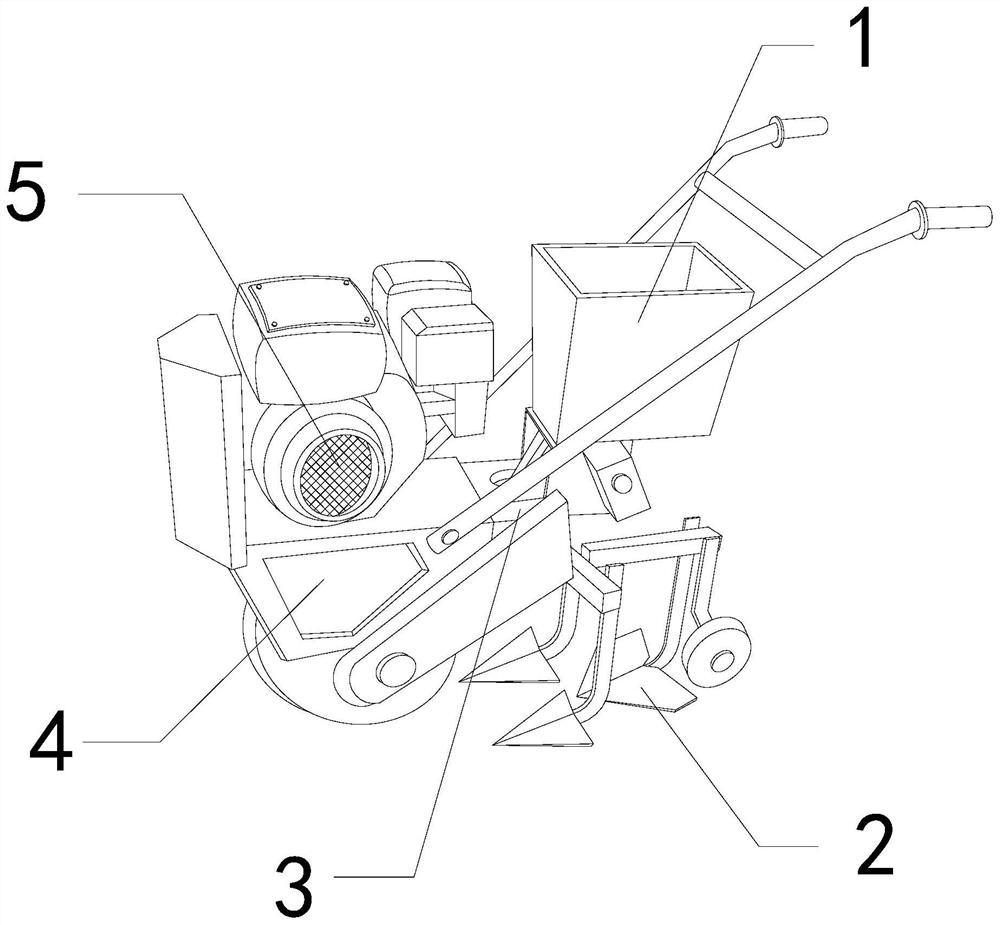
[0026] For example figure 1 -example Figure 5 Shown:

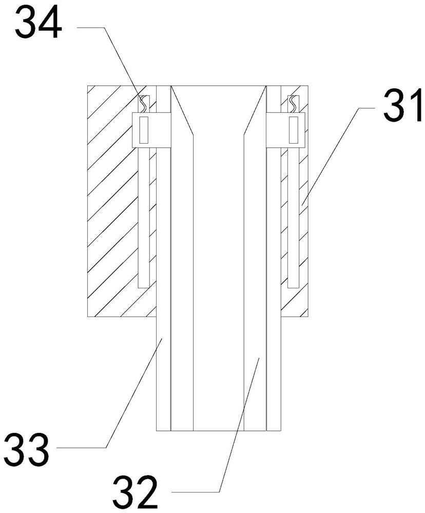
[0027] The present invention provides an agricultural machinery fertilizer, the structure of which includes a storage box 1, a ditching shovel 2, a discharge mechanism 3, a body 4, and a driver 5, the storage box 1 is installed at the upper end of the discharge mechanism 3, and the The ditching shovel 2 is welded to the body 4, the driver 5 is fixed on the upper end of the body 4, the discharge mechanism 3 and the body 4 are an integrated structure; the discharge mechanism 3 includes an outer frame 31, an inner tube 32 , an outer tube 33, a pullback bar 34, the inner tube 32 is engaged with the outer frame 31, the outer tube 33 and the outer frame 31 are an integrated structure, and the pullback bar 34 is installed on the inner tube 32 and the outer frame 31 Between boxes 31.

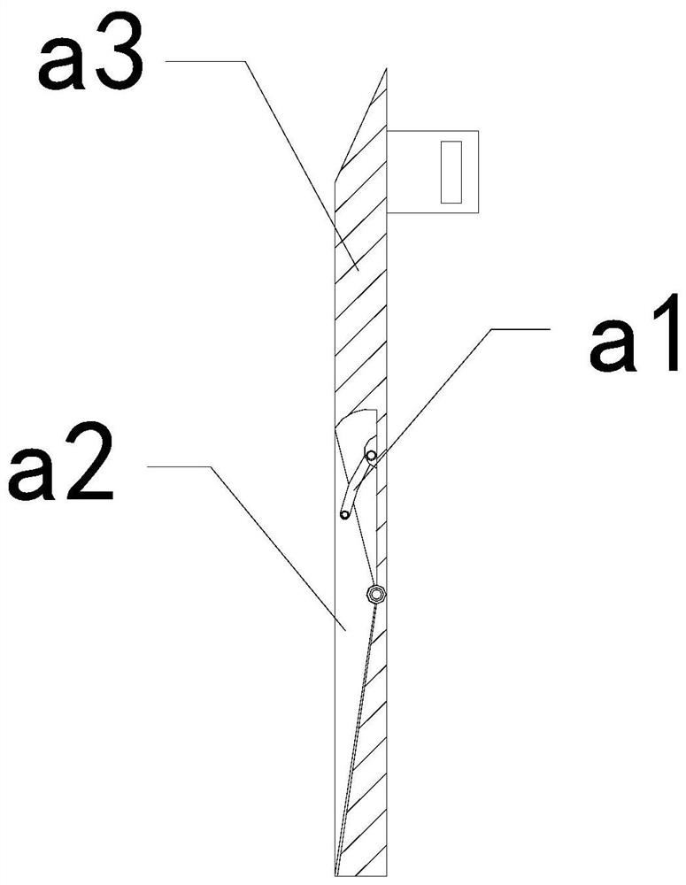
[0028] Wherein, the inner tube 32 includes a connecting rod a1, a force plate a2, and a plate surface a3, the connecting rod a1 is movably enga...

Embodiment 2

[0034] For example Image 6 -example Figure 8 Shown:

[0035] Wherein, the collection block b3 includes an outer frame b31, a clearing mechanism b32, and an opening and closing plate b33. The clearing mechanism b32 is installed at the right end of the outer frame b31, and the opening and closing plate b33 is hinged to the left end of the outer frame b31. The upper end of the outer frame b31 is provided with a hole through which the inside and outside are transparent, and the fertilizer collected by the outer frame b31 can be introduced into the inside of the outer frame b31 through the hole on the outer frame b31.

[0036] Wherein, the clearing mechanism b32 includes a bottom plate c1, an outer pusher frame c2, and a front plate c3, and the front plate c3 is movably engaged with the bottom plate c1 through the outer pusher frame c2, and the throwing force generated by the swing of the mechanism can The pusher frame c2 pushes the front plate c3 to protrude forward, so that t...


PUM


Abstract

The invention discloses an agricultural mechanical fertilizer applicator. The agricultural mechanical fertilizer applicator structurally comprises a storage box, a furrowing blade, a discharging mechanism, a machine body and a driver; the storage box is mounted at the upper end of the discharging mechanism; the furrowing blade is welded with the machine body; the driver is fixed at the upper end of the machine body; the discharging mechanism and the machine body are of an integrated structure; when the machine body makes a turn, the upper end of a stress plate can swing backwards through pushing force generated on the stress plate by the deviated fertilizer; therefore, a guide plate on the stress plate can guide the fertilizer back to the original position; the machine body is effectivelyprevented from throwing out the fertilizer outwards while quickly turning and turning around on the ground; the fertilizer can be guided into a collecting block through a hole in the upper portion ofan outer frame; an outward pushing frame can push a front-mounted plate forwards through the recoil, which is generated by pulling the collecting block to reset through a reset piece; and therefore, the front-mounted plate can extrude the fertilizer in the collecting block out of the space between two opening and closing plates.

Description

technical field [0001] The invention relates to the field of agriculture, in particular to an agricultural machinery fertilizer applicator. Background technique [0002] The agricultural fertilizer applicator is mainly used for fertilizing the agricultural planting land. It can open the land out of the groove through the ditching shovel at the bottom, and then guide the fertilizer inside the storage tank into the groove through the guide pipe, so as to complete the land fertilization. The fertilization work, based on the above description, the inventors found that the existing agricultural machinery fertilizer mainly has the following deficiencies, for example: [0003] When the agricultural fertilizer applicator is fertilizing, the fertilizer is continuously discharged downward from the feed pipe, and some of the fertilizers are so light that when the agricultural fertilizer applicator makes a quick turn on the land, the fertilizer will be thrown out , As a result, part of...

Claims


Application Information

Patent Timeline
Patent Type & Authority Applications(China)
IPC IPC(8): A01C5/06A01C15/00
CPCA01C5/062A01C15/00A01C15/008
Inventor 黄佳彬
Owner CHONGQING ACAD OF AGRI SCI
Why Eureka
Try Eureka