Vapor recovery system

An oil and gas recovery system and gas source technology, applied in separation methods, dispersed particle separation, chemical instruments and methods, etc., can solve the problem that the adsorption effect of the adsorption device is not ideal, the exhaust gas does not meet the domestic emission standards, oil tankers and shore work Safety hazards and other issues, to achieve excellent adsorption effect, increase residence time, and improve adsorption effect

Active Publication Date: 2022-03-01
CHINA HARBOUR ENGINEERING
View PDF8 Cites 0 Cited by
  • Summary
  • Abstract
  • Description
  • Claims
  • Application Information

AI Technical Summary

Problems solved by technology

Oil and gas are mainly hydrocarbons and sulfides, and the main component of hydrocarbons is CH 4 、C 2 h 6 、C 3 h 8 etc., are all flammable gases. If the oil and gas are dispersed in the atmosphere, not only will it pollute the atmosphere, but also when the temperature or pressure in the atmosphere is too high, the oil and gas will easily cause an explosion.
The oil tanker and shore work have great potential safety hazards. Therefore, during the loading process of the oil tanker at the wharf, it is necessary to adopt necessary devices to recover oil and gas.
At present, the oil and gas recovery system mostly adopts the method of adsorption and condensation, but the adsorption effect of the adsorption device is not ideal, which brings a greater load to the later condensation, and even the final exhaust gas cannot meet the domestic emission standards, let alone the more stringent ones. Foreign emission standards

Method used


Image

  • Vapor recovery system
  • Vapor recovery system
  • Vapor recovery system

Examples


Embodiment Construction

[0031] The present invention will be further described in detail below in conjunction with the accompanying drawings, so that those skilled in the art can implement it with reference to the description.

[0032] It should be noted that in the description of the present invention, the orientation or positional relationship indicated by the term is based on the orientation or positional relationship shown in the drawings, which is only for the convenience of describing the present invention and simplifying the description, and does not indicate or imply No device or element must have a specific orientation, be constructed, and operate in a specific orientation and therefore should not be construed as limiting the invention.

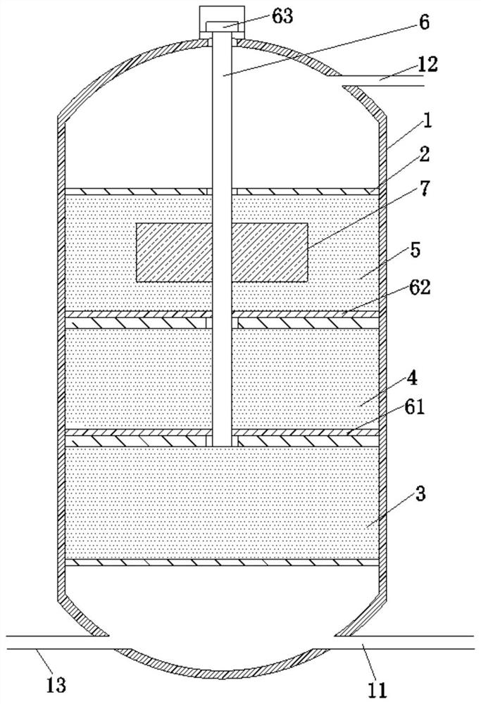
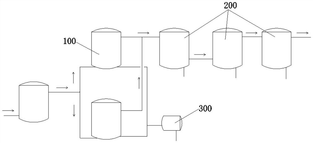
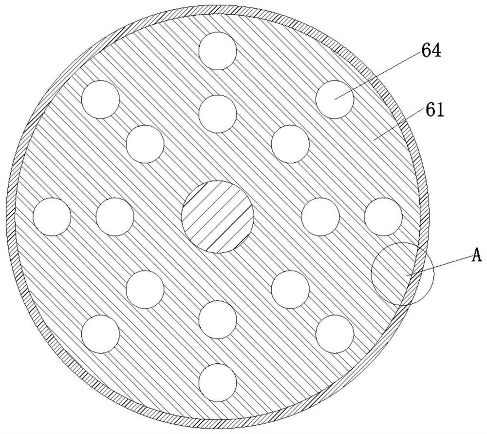
[0033] Such as Figure 1~5 As shown, the present invention provides a kind of oil gas recovery system, comprising:

[0034] At least one adsorption tank 100, when there are two or more adsorption tanks 100, when one adsorption tank 100 is saturated, the ov...


PUM

PropertyMeasurementUnit
diameteraaaaaaaaaa
diameteraaaaaaaaaa

Abstract

The invention discloses an oil and gas recovery system, comprising: an adsorption tank, which includes: a tank body, the bottom of which is provided with an air inlet pipe and an air outlet pipe I, and the top is provided with an air outlet pipe II; four horizontal plates are arranged at intervals in the middle of the tank body , the tank is divided into intake chamber, adsorption chamber Ⅰ, adsorption chamber Ⅱ, adsorption chamber Ⅲ, and gas outlet chamber in turn. There are multiple through holes Ⅰ on the horizontal plate, and the adsorption chamber Ⅰ, adsorption chamber Ⅱ, and adsorption chamber Ⅲ Both are filled with adsorbent; the upper end of the rotating rod is sealed and rotated to pass through the top of the tank body, and the lower end rotates through the two upper horizontal plates and is connected to the third horizontal plate in rotation. The rotating rod is driven by a motor to rotate. Rotary plate Ⅰ and rotary plate Ⅱ are set respectively, and through-holes Ⅱ are provided on the rotary plate Ⅰ and the rotary plate Ⅱ; multiple pulp plates are fixed on the rotary rod and located in the adsorption chamber Ⅲ, and there are multiple through-holes on the pulp plate. Hole III; condensing assembly. The invention has the beneficial effect of improving the adsorption efficiency of the adsorption tank.

Description

technical field [0001] The invention relates to the technical field of oil gas recovery. More specifically, the present invention relates to an oil vapor recovery system. Background technique [0002] During the loading process of oil tankers at the wharf, a large amount of oil and gas will be produced. Oil and gas are mainly hydrocarbons and sulfides, and the main component of hydrocarbons is CH 4 、C 2 h 6 、C 3 h 8 etc., are all flammable gases. If oil and gas are dispersed in the atmosphere, it will not only pollute the atmosphere, but also cause explosions easily when the temperature or pressure in the atmosphere is too high. The oil tanker and shore work have great potential safety hazards. Therefore, during the loading process of the oil tanker at the wharf, it is necessary to adopt necessary devices to recover oil and gas. At present, the oil and gas recovery system mostly adopts the method of adsorption and condensation, but the adsorption effect of the adsorpt...

Claims


Application Information

Patent Timeline
Patent Type & Authority Patents(China)
IPC IPC(8): B01D53/06
CPCB01D53/06B01D2253/102
Inventor 张化强
Owner CHINA HARBOUR ENGINEERING
Why Eureka
Try Eureka