
Speed chain assembly line

An assembly line and double-speed chain technology, applied in the direction of conveyors, conveyor objects, transportation and packaging, etc., can solve problems that affect the assembly of parts, easy to detach from the surface of the tooling board, and shape changes

Inactive Publication Date: 2020-11-27
泉州市启明电子设备有限公司
View PDF6 Cites 3 Cited by
  • Summary
  • Abstract
  • Description
  • Claims
  • Application Information

AI Technical Summary

Problems solved by technology

[0002] After the production and processing of the parts is completed, the parts are conveyed and assembled, and the parts are placed on the tooling plate of the double-speed chain assembly line to support the parts. The double-speed chain drives the running parts to run, and the transmission speed of the parts is changed by changing the rotation speed of the double-speed chain Finally, stop at the corresponding position through the stopper; when using the double-speed chain assembly line to transport parts in the prior art, due to the change of the transmission speed of the assembly line, and the outer smooth and round shape of some parts, the transportation speed of the tooling plate is accelerated and stops suddenly through the stopper , causing the parts to move forward due to the inertial force, and it is easy to fall off the surface of the tooling plate, which makes the surface of the parts collide, changes the shape, and affects the assembly between the parts

Method used


Image

  • Speed chain assembly line
  • Speed chain assembly line
  • Speed chain assembly line

Examples


Embodiment 1

[0025] as attached figure 1 to attach Figure 5 Shown:

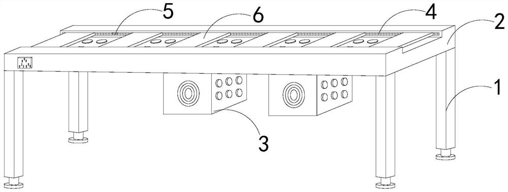
[0026] The invention provides a double-speed chain assembly line, the structure of which includes a support frame 1, a workbench 2, a distribution box 3, a chain 4, a blocking block 5, and a tooling plate 6. The workbench 2 is fixed on the top of the support frame 1, and the The distribution box 3 is installed at the bottom of the workbench 2, the chain 4 is installed on both sides inside the workbench 2, the blocking block 5 is fixed on the left inner wall of the workbench 2, and the tooling plate 6 is arranged on the top of the workbench 2, And cooperate with chain 4 activities.

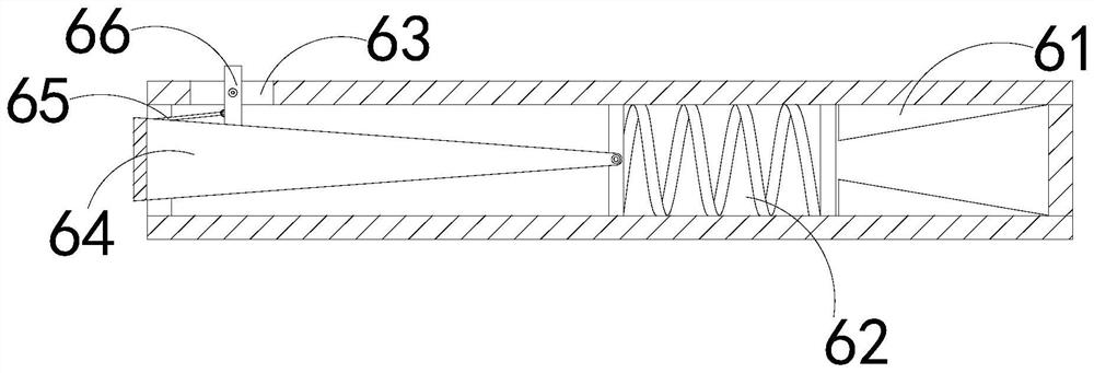
[0027] The tooling plate 6 is provided with a block 61, a spring 62, an opening 63, a push block 64, a push rod 65, and a block 66. The block 61 is fixed on the inner wall on the right side of the tooling plate 6, and the spring 62 is located on the card. On the left side of the block 61, the opening 63 runs through the top of the left end...

Embodiment 2

[0034] as attached Image 6 to attach Figure 7 Shown:

[0035]Wherein, the opening 63 is provided with a side block n1, clamping teeth n2, and a pull cord n3, the side block n1 is fixed in the middle of the inner side of the opening 63, the clamping teeth n2 are located on the upper and lower sides of the side block n1, and the pull cord n3 Connected between the clamping teeth n2 and the inner wall of the opening 63, the clamping teeth n2 are provided with four, and are in a triangular shape. The pressure is beneficial to limit the stopper 66.

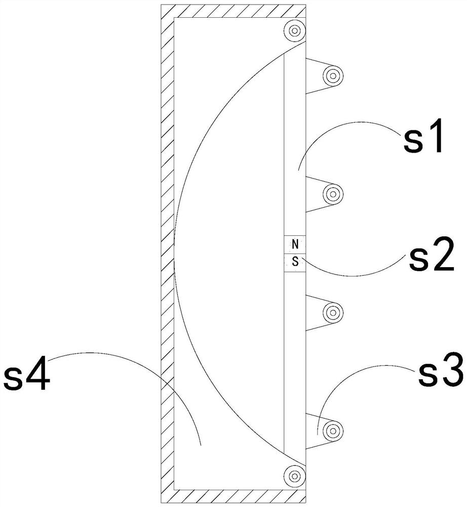
[0036] Wherein, the side block n1 is provided with a fixed block m1, a contact plate m2, a tooth plate m3, a pressing block m4, and an elastic block m5, the fixed block m1 is fixed on the inner wall of the left end of the side block n1, and the contact plate m2 is installed on Inside the side block n1, the tooth plate m3 is arranged on the left side of the contact plate m2, the pressure block m4 is fixed on the right side of the co...


PUM


Abstract

The invention discloses a speed chain assembly line. The speed chain assembly line structurally comprises a supporting frame, a workbench, a distribution box, a chain, a stop block and a tool plate, wherein the workbench is fixed to the top of the supporting frame, the distribution box is installed at the bottom of the workbench, due to fact that conveying speed of the assembly line is changed andexteriors of a part of parts are smooth and round, conveying speed of the tool plate is increased, when tool plate suddenly stops when passing through the stop block and collides with the stop block,the stop blocks stop and clamp the parts, so that the situation that the parts move forwards under the action of inertia force and are likely to be disengaged from the surface of the tool plate to fall off, the surfaces of the parts collide, the shapes are changed, and assembling of the parts is affected is reduced, a check block is limited through a side block and clamping teeth in an opening, the situation that when a part collides with the check block, normal clamping and blocking of the part are affected due to the fact that the position of the check block is prone to being changed is relieved, and the situation that the position of the check block is changed due to collision force, and normal movement of the tool plate is affected is reduced.

Description

technical field [0001] The invention belongs to the field of differential speed chain assembly line, and more specifically, relates to a double speed chain assembly line. Background technique [0002] After the production and processing of the parts is completed, the parts are conveyed and assembled, and the parts are placed on the tooling plate of the double-speed chain assembly line to support the parts. The double-speed chain drives the running parts to run, and the transmission speed of the parts is changed by changing the rotation speed of the double-speed chain Finally, stop at the corresponding position through the stopper; when using the double-speed chain assembly line to transport parts in the prior art, due to the change of the transmission speed of the assembly line, and the outer smooth and round shape of some parts, the transportation speed of the tooling plate is accelerated and stops suddenly through the stopper , causing the parts to move forward due to the ...

Claims


Application Information

Patent Timeline
Patent Type & Authority Applications(China)
IPC IPC(8): B65G17/34B65G17/42B65G17/46B65G21/20B65G47/22B65G47/88
CPCB65G17/34B65G17/42B65G17/46B65G21/2063B65G47/22B65G47/8861
Inventor 叶贤良
Owner 泉州市启明电子设备有限公司
Learn More