

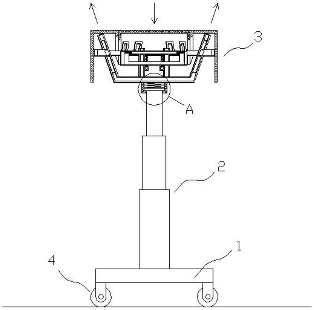
A lifting platform for central air-conditioning indoor unit auxiliary installation equipment
A technology for installing equipment and central air-conditioning. It is applied in the direction of lifting frame and lifting device, which can solve the problems of high installation cost, indoor unit slipping and falling, and potential safety hazards, and achieve the effect of convenient use and ingenious and compact structure design.
- Summary
- Abstract
- Description
- Claims
- Application Information
AI Technical Summary
Problems solved by technology
Method used
Image

Examples
Embodiment Construction
[0033] In order to make the purpose, technical solutions and advantages of the embodiments of the present invention more clear, the technical solutions in the embodiments of the present invention will be clearly and completely described below in conjunction with the drawings in the embodiments of the present invention.
[0034] In the description of the present invention, it should be noted that unless otherwise specified, the meaning of "plurality" is two or more; the terms "upper", "lower", "left", "right", "inner ", "outside", "front end", "rear end", "top", "bottom" and other indicated orientations or positional relationships are based on the orientations or positional relationships shown in the drawings, and are only for the convenience of describing the present invention and simplifying the Describes, but does not indicate or imply that the device or element referred to must have a specific orientation, be constructed in a specific orientation, and operate in a specific o...
PUM
 Abstract
Description
Claims
Application Information