A smart water supply system

A technology of water supply system and water affairs, applied in water supply installations, water/sewage treatment, water/sewage multi-stage treatment, etc., can solve the problems of consuming manpower, accelerating the rate of corrosion of the water storage tank, and reducing the service life of the water storage tank. , to achieve the effect of improving the degree of cleaning, reducing the corrosion rate and optimizing the use process

Active Publication Date: 2021-06-22
安徽皖水水务发展有限公司
View PDF8 Cites 0 Cited by
  • Summary
  • Abstract
  • Description
  • Claims
  • Application Information

AI Technical Summary

Problems solved by technology

[0003] Due to the lack of corresponding water storage tank cleaning mechanism in the actual application process of water supply equipment currently on the market, a layer of dirt will adhere to the inner wall of the water storage tank after long-term use, and at the same time, the interior of the water storage tank will be degraded by the action of chloride ions in the water. Rust occurs. If these rust and dirt cannot be cleaned in time, a large number of bacteria will grow and pollute the water inside the water storage tank. At the same time, these rust and dirt will also accelerate the rate of corrosion of the water storage tank. It affects the quality of water supply, but for its cleaning, it cannot achieve convenient and fast results, and it consumes a lot of manpower, thereby reducing the service life of the water storage tank
The present invention belongs to an improved patent, which is a further improvement of the applicant on the basis of his own technical solution, especially for the surface of the electric heating rod in the transfer box after long-term use, although there is washing with cleaning liquid, there may still be fouling over time layer, and the fouling layer will hinder the heating effect of the electric heating rod, which further affects the cleaning effect of the circulating cleaning structure on the system, forming a vicious circle, so it is necessary to have a mechanical external force to regularly remove the dirt on the surface of the electric heating rod

Method used


Image

  • A smart water supply system
  • A smart water supply system
  • A smart water supply system

Examples


Embodiment

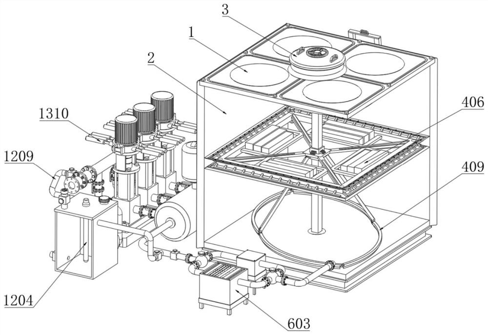
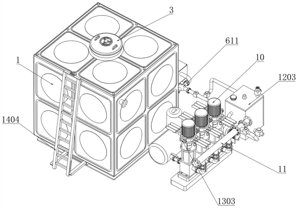
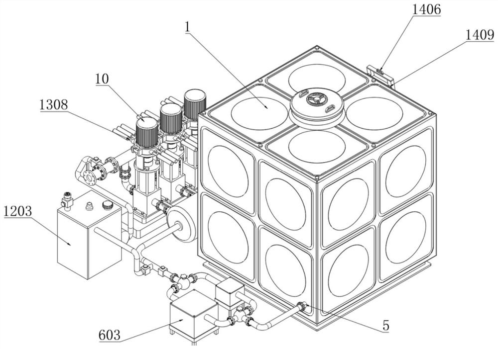
[0039] Example: as Image 6 , 7 , 10-12, including the water tank shell 1, the water tank inner wall cleaning mechanism 4, the continuous disinfection and filtering mechanism 6, the circulating cleaning structure 12, the shock absorption buffer mechanism 13 and the protective storage mechanism, the top wall of the transfer box 1203 of the circulating cleaning structure 12 is fixed. There are two pneumatic lifting cylinders 1211 that act synchronously. The output shaft 1225 of the pneumatic lifting cylinder is fixedly connected with the installation ring plate 1212 inside the transfer box 1203. The upper end of the installation ring plate 1212 is provided with a placement groove 1213, and a bottom is placed in the placement groove 1213. Ring 1214, the inner wall of the bottom ring 1214 is fixed with a brush wire 1215, and the bottom ring 1214 is fixed with a plurality of transmission cylinders 1216, and the two adjacent transmission cylinders 1216 are fixedly connected by at le...


PUM


Abstract

The invention discloses a smart water supply system. The top wall of the transfer box of the circulation cleaning structure is fixed with two synchronously acting pneumatic lifting cylinders, the output shaft of the pneumatic lifting cylinder is fixedly connected with the installation ring plate inside the transfer box, and the installation ring There is a placement groove on the top of the board, and a bottom ring is placed in the placement groove. The inner wall of the bottom ring is fixed with brush wires, and a plurality of transmission cylinders are fixed on the bottom ring. At least two connecting cylinders are connected between two adjacent transmission cylinders. The rod is fixedly connected, and the upper end of the transmission cylinder at the top is fixedly connected with a sealing ring outside the transfer box. The outer wall of each transmission cylinder has a transmission rack, and the top wall of the transfer box is fixed with a transmission motor. The output shaft of the transmission motor is fixed. Connect the gear, the gear can be meshed with the transmission rack, the top wall of the transfer box is provided with a ring hole for the transmission cylinder to pass through, the top of the two pneumatic lifting cylinders is fixed with a cross bar, and the bottom end of the cross bar is fixed with a bottom opening The internally threaded cylinder, the internally threaded cylinder is sleeved with the positioning screw fixedly connected to the top of the electric heating rod.

Description

technical field [0001] The invention relates to the technical field of water affairs and water supply, in particular to a smart water affairs and water supply system. Background technique [0002] The water supply system refers to a complex that provides water resources to different water departments according to certain water quality requirements. The water supply system can be divided into domestic water supply system, production water supply system, fire protection water supply system and shared water supply system. Domestic water for drinking, cooking and washing in public buildings and industrial enterprises, the water supply system is composed of water supply equipment; [0003] Due to the lack of corresponding water storage tank cleaning mechanism in the actual application process of water supply equipment currently on the market, a layer of dirt will adhere to the inner wall of the water storage tank after long-term use, and at the same time, the interior of the wate...

Claims


Application Information

Patent Timeline
Patent Type & Authority Patents(China)
IPC IPC(8): B08B9/087E03B11/00C02F9/08
CPCB08B9/0861B08B9/087C02F1/001C02F1/283C02F1/32C02F9/00E03B11/00
Inventor 许方方张朝臣唐晓晖
Owner 安徽皖水水务发展有限公司
Why Eureka
Try Eureka