Device for filtering solids from liquids

A liquid and material technology, applied in the field of devices for filtering out substances, can solve the problems of growth and premature decline of filtration efficiency, and achieve the effect of uniform filter residue growth

Inactive Publication Date: 2007-09-26
MICRODYN NADIR
View PDF3 Cites 2 Cited by
  • Summary
  • Abstract
  • Description
  • Claims
  • Application Information

AI Technical Summary

Problems solved by technology

The edge suction disclosed for example in WO 03 / 037489 A1 therefore favors the growth of the filter residue at the edge of the filter element, leading to a premature drop in the filtration efficiency

Method used


Image

  • Device for filtering solids from liquids
  • Device for filtering solids from liquids
  • Device for filtering solids from liquids

Examples


Embodiment Construction

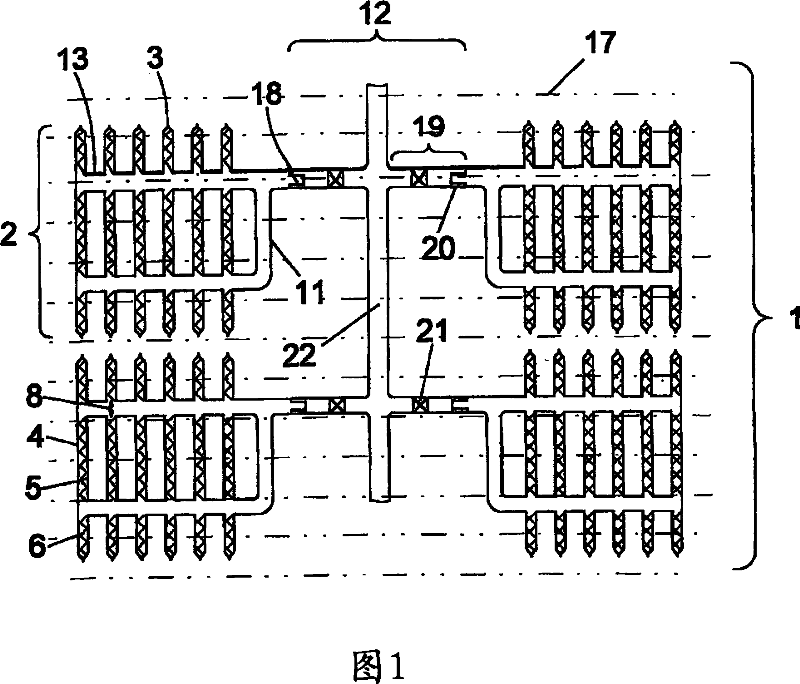
[0033]As can be seen from FIG. 1 , the device 1 consists of a plurality of filter modules 2 with filter elements 3 which are designed as flat film bags and which are surrounded or flow around by the liquid to be filtered. The filter elements 3 are arranged in parallel and at a certain distance from each other, and are pressure-tightly connected to each other by connecting elements 13, wherein the connecting elements 13 are connected to the output holes 8 on the filter elements 3, and the permeate outlets 11 of each filter module 2 are connected by means of a The connector 18 is connected to the permeate collector 12 . The permeate collector 12 includes a main conduit 22 from which a connection pipe 19 branches off. The connecting pipe 19 is equipped with a connector seat 20 and a valve 21 . In the connected state, the connector 18 and the connector seat 20 form a pressure-tight connection between the permeate outlet 11 and the permeate collector 12 .

[0034] The flow of per...


PUM


Abstract

The invention relates to a device for filtering liquids, comprising parallel planar membrane pockets and means for pressure-tight connection of the membrane pockets and for coupling of a suction. The membrane pockets contain a drainage element with a planar connection to two membranes which is pressure-tight around the edges. Adjacent membrane pockets are connected together and to the suction by means of one or more drain drillings and corresponding lines. The drain drillings are so arranged that the trans-membrane pressure difference falls only slightly across the area of the membrane pocket.

Description

technical field [0001] The invention relates to a device for filtering substances from liquids by means of microfiltration, ultrafiltration and nanofiltration, comprising a plurality of filter modules consisting of filter elements designed as flat film bags and surrounded by the liquid to be filtered, wherein the filter elements Arranged in parallel and at a distance from each other and connected to each other through outflow holes and connecting elements, the device also includes a permeate outlet of each filter module and a permeate collector connected to the permeate outlet of the filter module. Background technique [0002] A common filter system for cleaning waste water consists of a filter unit with a tubular or box-shaped housing with upper and lower openings, in which a number of flat filter elements are arranged vertically and in parallel at a certain distance from each other. The intermediate spaces between the individual filter elements form flow-through channels....

Claims


Application Information

Patent Timeline
Patent Type & Authority Applications(China)
IPC IPC(8): B01D63/08B01D65/00
CPCB01D2315/06B01D63/081B01D63/084
Inventor R·福格特U·迈尔-布卢门洛特J·里普尼茨基
Owner MICRODYN NADIR
Why Eureka
Try Eureka