
Auxiliary structure of wind generating set tower

A technology for wind turbines and auxiliary structures, which is applied in the monitoring of wind turbines, wind turbines, installation/support configuration of wind turbines, etc. It can solve the problems of unfavorable refrigerant equipment heat dissipation, large volume, high temperature, etc., to reduce sunlight radiation and The impact of waves on the tower, the effect of enhancing wind load resistance and reducing maintenance times

Pending Publication Date: 2020-11-27
华润电力技术研究院有限公司
View PDF0 Cites 0 Cited by
  • Summary
  • Abstract
  • Description
  • Claims
  • Application Information

AI Technical Summary

Problems solved by technology

Most of the towers are cylindrical, polygonal and other structures. Because of their large volume, high height, and high wind speed, when the wind load is large, especially in the wind field with large turbulent flow and high wind shear coefficient, the structure of the tower Severe wind load test; in addition, due to the large surface area of ​​the tower, especially in the wind field with high ultraviolet intensity, the tower receives a large amount of sunlight radiation, the tower is relatively sealed, and the obvious greenhouse effect makes the inner temperature of the tower higher ; It is not conducive to the heat dissipation of the equipment inside the tower and the equipment that uses the air inside the tower as the refrigerant

Method used


Image

  • Auxiliary structure of wind generating set tower
  • Auxiliary structure of wind generating set tower
  • Auxiliary structure of wind generating set tower

Examples


Embodiment Construction

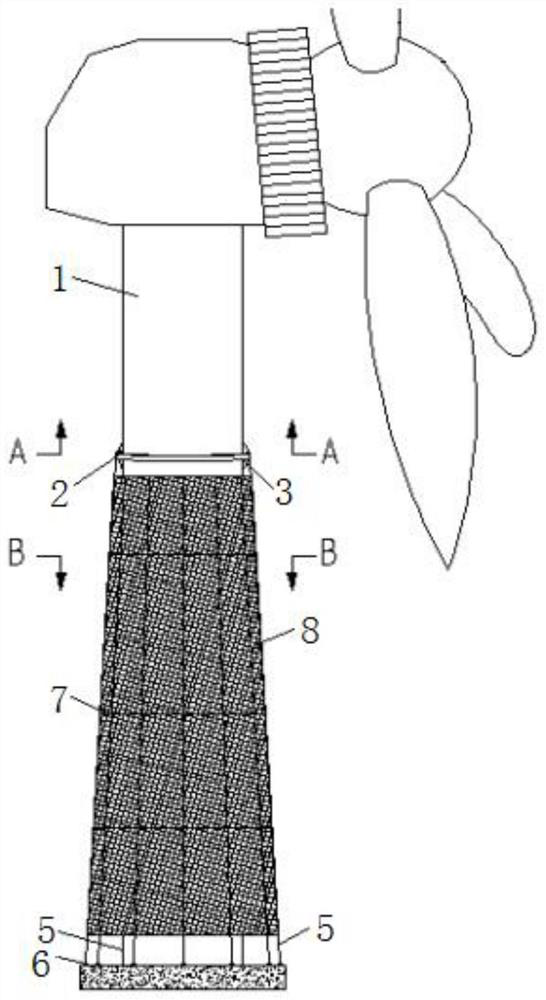
[0025] It should be noted that the orientation words "up, down, horizontal, vertical" in this article refer to figure 1 The up, down, horizontal and vertical directions in the middle. The location words appearing in this article are all established on the basis of the habitual usage of those skilled in the art and the drawings in the specification, and their appearance should not affect the protection scope of the present invention.

[0026] In order to enable those skilled in the art to better understand the solution of the present invention, the present invention will be further described in detail below with reference to the accompanying drawings and specific embodiments.

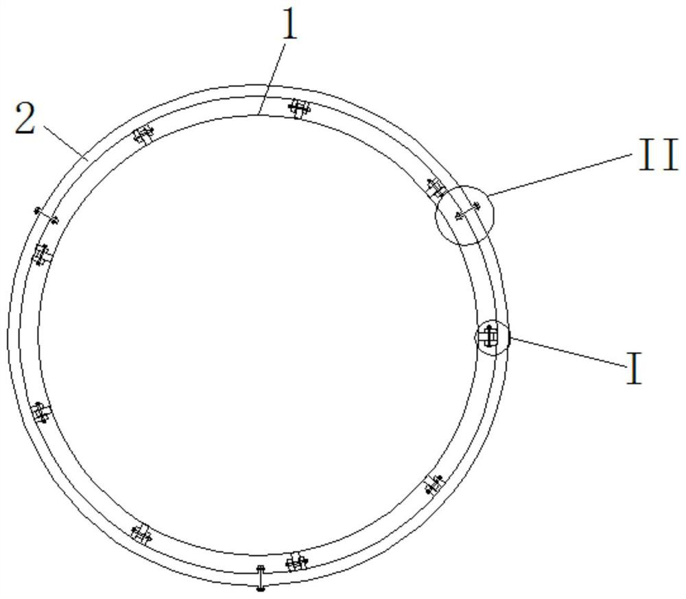
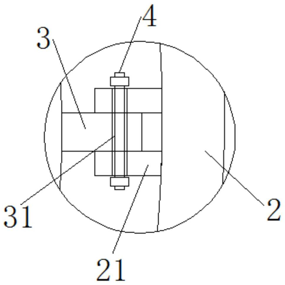
[0027] Please refer to Figure 1 to Figure 9 , figure 1 It is a schematic diagram of the auxiliary structure of the wind turbine tower provided by the present invention; figure 2 for figure 1 Sectional view of A-A; image 3 for figure 2 Enlarged view of middle I; Figure 4 for figure 2 Enlarged view of mid...


PUM


Abstract

The invention provides an auxiliary structure of a wind generating set tower. The auxiliary structure comprises a mounting ring arranged on the outer wall of the tower in a sleeving manner. A plurality of connecting parts are fixedly mounted on the inner side wall of the mounting ring in the circumferential direction. A plurality of lifting lugs are fixedly mounted on the outer wall of the tower in the circumferential direction, wherein the number of the lifting lugs is equal to that of the connecting parts. Each lifting lug is provided with at least one bolt hole. The bolt holes are transversely formed. The mounting ring and the connecting parts are connected and fixed through bolts. The mounting ring is provided with a plurality of mounting holes which are used for mounting and fixing astay cable and distributed in the circumferential direction. One end of the stay cable is connected with the mounting ring, and the other end of the stay cable is connected with an anchoring point located on tower footing concrete. A plurality of circles of net ribs are fixedly arranged on the stay cable. The stay cable and the net ribs are provided with net-shaped porous cloth. All positions of the tower are covered with the net-shaped porous cloth. By means of the auxiliary structure, the wind load resistance of the wind generating set tower is remarkably improved, influences of sunlight radiation and sea waves on the tower are reduced, the maintenance frequency of the tower is reduced, and the service life of the tower is prolonged.

Description

Technical field [0001] The invention relates to the technical field of wind power generation, and more specifically, to an auxiliary structure of a wind power generating set tower. Background technique [0002] The tower of a wind turbine is an important component, and its main function is to support the nacelle, generator and impeller components. Most of the towers are cylindrical, polygonal and other structures. Because of their large volume, high height, and high wind speed, the tower is constructed when the wind load is large, especially the wind field with high turbulence and high wind shear coefficient. Severe wind load test; in addition, due to the large surface area of ​​the tower, especially in the wind field with high ultraviolet intensity, the tower receives a lot of solar radiation, the tower is relatively sealed, and the obvious greenhouse effect makes the internal temperature of the tower higher ; It is not conducive to the heat dissipation of the equipment inside ...

Claims


Application Information

Patent Timeline
IPC IPC(8): F03D13/20F03D17/00
CPCF03D13/20F03D17/00Y02E10/72Y02E10/728
Inventor 周幼辉刘桥余维
Owner 华润电力技术研究院有限公司
Learn More