A road level detection device for tunnel detection

A technology for leveling detection and tunneling, applied in measuring devices, instruments, etc., can solve problems such as poor adaptability, low detection efficiency, and increased labor.

Active Publication Date: 2022-04-15
贵州顺康检测股份有限公司
View PDF8 Cites 0 Cited by
  • Summary
  • Abstract
  • Description
  • Claims
  • Application Information

AI Technical Summary

Problems solved by technology

[0002] The quality of tunnel construction directly affects the safety of people traveling, so tunnel inspection is a very important link, and the inspection of road surface roughness is very important in tunnel inspection. The conventional road surface roughness should be within 20mm, while the traditional Most of the detection is to use a 2m ruler to detect two places every 10m, which not only increases the labor load, but also increases the working time. At the same time, unavoidable visual errors will occur when people watch with the naked eye. For this reason, people invented the detection Machines, for example, the Chinese utility model patent No. 2019207771889 discloses a tunnel inspection vehicle and a tunnel inspection robot. In the lower setting, the two ends of the U-shaped frame body are provided with first running parts. The first running parts are used to drive the U-shaped frame body to move along the direction of the tunnel. Several brackets are detachably connected to the U-shaped frame body. The brackets are arranged at intervals, and each bracket is used to install the detection device; through the U-shaped brackets that match the shape of the inner wall of the tunnel, the inner space and passages of the tunnel are reserved to meet the passage of other operators and equipment inside the tunnel. U Brackets are distributed on the shaped frame body, and the brackets are used to install the detection device. When the U-shaped frame body moves with the first walking part, the detection device sweeps the inner wall of the tunnel. The tunnel detection vehicle has simple structure, convenient operation and good effect;
[0003] However, through the study of the above examples, it is found that the existing detection equipment can only be installed on a fixed type of detection vehicle, and can only detect fixed size tunnels, resulting in poor adaptability and low detection efficiency. Therefore, there is an urgent need to invent a function of automatically detecting the smoothness of the road surface, and at the same time, the angle can be adjusted to solve the above problems.

Method used


Image

  • A road level detection device for tunnel detection
  • A road level detection device for tunnel detection
  • A road level detection device for tunnel detection

Examples


Embodiment Construction

[0039] In order to make the technical means, creative features, goals and effects achieved by the present invention easy to understand, the present invention will be further described below in conjunction with specific embodiments.

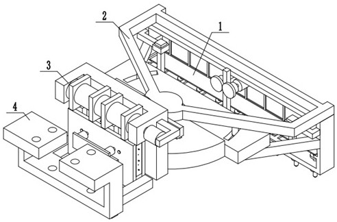
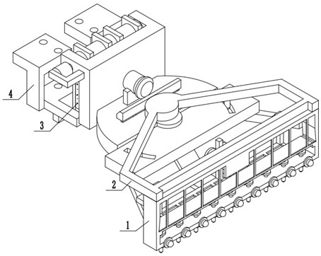
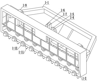
[0040] Examples such as Figure 1-17 As shown, a road level detection device for tunnel detection includes a detection mechanism 1, a steering drive mechanism 2, a lifting drive mechanism 3, a fixing mechanism 4 and an intelligent control box, and the steering drive mechanism 2 is fixedly installed on the upper end of the detection mechanism 1 , the steering drive mechanism 2 is fixedly installed on the lifting drive mechanism 3, the lifting drive mechanism 3 is fixedly installed on the fixed mechanism 4, and the intelligent control box is installed on the fixed mechanism 4, which is controlled by PLC. The device has its own power supply or The power source of the vehicle body is externally connected to obtain a power source; the detection mechani...


PUM


Abstract

The present invention relates to a related device for tunnel detection, specifically a road level detection device for tunnel detection, including a detection mechanism, a steering drive mechanism, a lifting drive mechanism and a fixing mechanism, and the steering drive mechanism is fixedly installed on the detection On the upper end of the mechanism, a steering drive mechanism is installed on the lifting drive mechanism. The lifting drive mechanism is fixedly installed on the fixed mechanism. It has the function of automatically detecting the smoothness of the road surface, and can adjust the angle at the same time to adapt to tunnels of different sizes.

Description

technical field [0001] The invention relates to the technical field of tunnel detection, in particular to a road level detection device for tunnel detection. Background technique [0002] The quality of tunnel construction directly affects the safety of people traveling, so tunnel inspection is a very important link, and the inspection of road surface roughness is very important in tunnel inspection. The conventional road surface roughness should be within 20mm, while the traditional Most of the detection is to use a 2m ruler to detect two places every 10m, which not only increases the labor load, but also increases the working time. At the same time, unavoidable visual errors will occur when people watch with the naked eye. For this reason, people invented the detection Machines, for example, the Chinese utility model patent No. 2019207771889 discloses a tunnel inspection vehicle and a tunnel inspection robot. In the lower setting, the two ends of the U-shaped frame body a...

Claims


Application Information

Patent Timeline
Patent Type & Authority Patents(China)
IPC IPC(8): G01B21/30
CPCG01B21/30
Inventor 陈娜
Owner 贵州顺康检测股份有限公司
Why Eureka
Try Eureka