Telegraph pole support

A technology for utility poles and electric push rods, applied in the field of utility pole brackets, which can solve the problems of unstable support, inability to adjust the concave position, and small static friction force at the contact point between the support device and the ground, so as to achieve firm support, simple structure, and convenience The effect of daily maintenance

Inactive Publication Date: 2020-08-21
国网河南省电力公司桐柏县供电公司
View PDF7 Cites 2 Cited by
  • Summary
  • Abstract
  • Description
  • Claims
  • Application Information

AI Technical Summary

Problems solved by technology

[0003] The Chinese utility model patent whose publication number is CN208584508U discloses a pole support device, which includes a support body and a support frame for supporting the support body. The support body includes a support body base surface and a support body bottom surface. The top of the surface is provided with a concave position adapted to the pole, and an elastic device is provided between the base surface of the support body and the bottom surface of the support body. The support frame includes a plurality of telescopic support rods whose tops are connected to the bottom surface of the support body. The rod includes a supporting inner rod and a supporting outer rod. The supporting inner rod is connected to the inside of the supporting outer rod. The overall connection of the device is stable, but the orientation of the concave position cannot be adjusted according to the inclination angle of the electric pole, and the supporting device and the The static friction force at the ground contact point is small, and the support is not stable

Method used


Image

  • Telegraph pole support
  • Telegraph pole support
  • Telegraph pole support

Examples


Embodiment 1

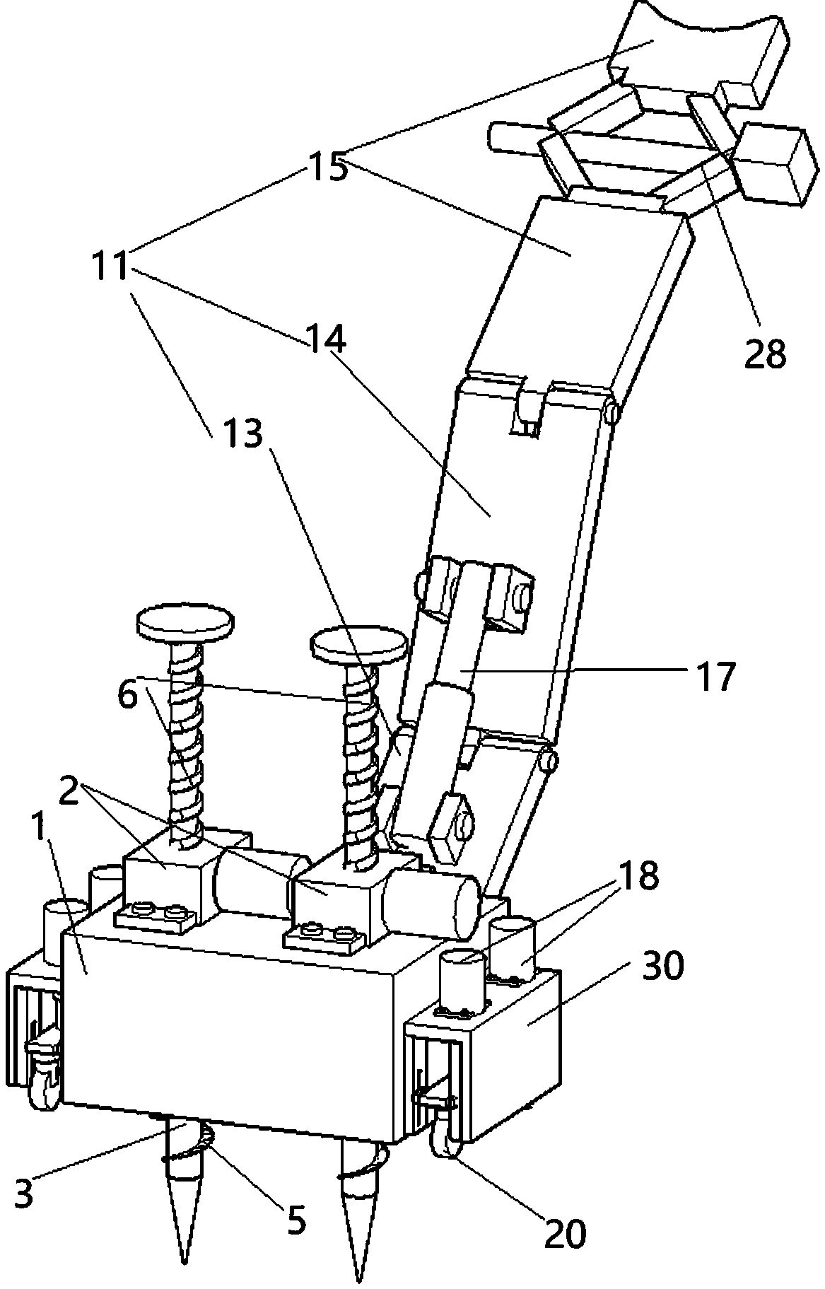
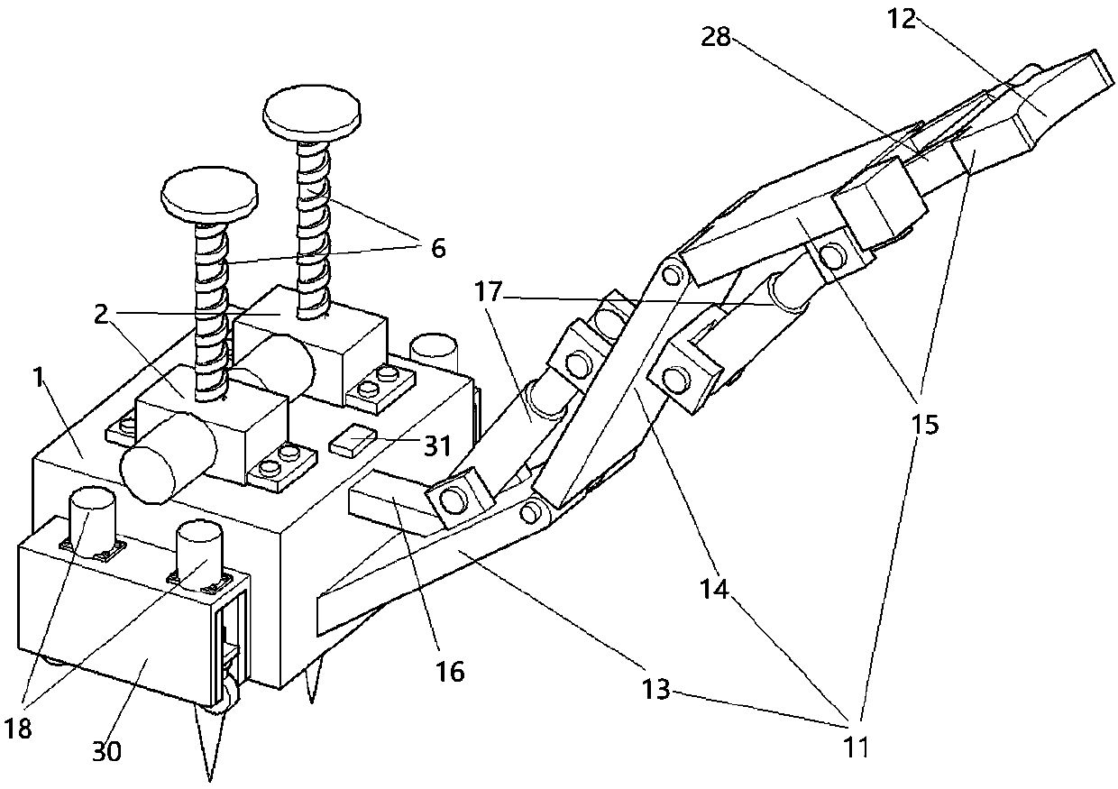
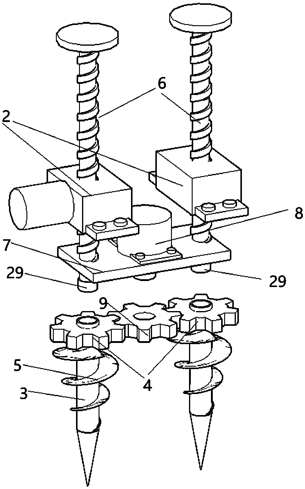
[0031] Such as Figure 1-4 Shown is the first embodiment of the present invention, a utility pole bracket, including a fixed box 1, the fixed box 1 is a cuboid shell-shaped structure welded by eight steel plates, and two spirals are fixed on the top plate of the fixed box 1 The motor of lift 2, such as image 3 As shown, the lower end of the screw rod 6 of the screw jack 2 is located in the fixed box, the screw rod 6 is perpendicular to the ground, and the screw rod 6 is provided with an anti-rotation groove. The bottom end of the screw rod 6 is rotated to connect the connecting rod 3, and the connection method is as follows: a bearing 29 is welded on the bottom end of the screw rod 6, and the bearing 29 is a deep groove ball bearing. The upper part of the connecting rod 3 is welded to the gear one 4, and the middle part of the connecting rod 3 is welded to the spiral blade 5. The radius of the spiral blade 5 gradually decreases from top to bottom. Get two through holes 1 th...

Embodiment 2

[0035] Such as Figure 5 and Figure 6 Shown is the second embodiment of the present invention. The difference between this embodiment and Embodiment 1 is that the left side of the fixed box 1 is provided with an accommodation box 22, and the accommodation box 22 is a rectangular parallelepiped shell-like structure with openings at both ends. The accommodation box 22 The right side plate is welded on the fixed box 1 left side wall, and the bottom surface of the accommodation box 22 and the bottom surface of the fixed box 1 are located on the same plane. Moving plate 23 is set in the accommodation box 22, and moving plate 23 is a rectangular plate, and a plurality of ground nails 26 are evenly welded on the bottom surface of the moving plate 23, and the through holes 27 matched with the ground nails are punched out on the bottom surface of the accommodation box 22 by a puncher. The driving device that drives the moving board 23 to move up and down is set on the top surface of ...

Embodiment approach

[0038] Such as Figure 7 Shown is the third embodiment of the present invention. The difference between this embodiment and Embodiment 1 is that the left side of the fixed box 1 has an opening, the opening is hinged to close the door 21, and the other end of the closed door 21 is fixed by a door lock. Box 1 is detachably connected.


PUM


Abstract

The invention discloses a telegraph pole support. The telegraph pole support comprises a fixing box, wherein a spiral elevator is arranged on the fixing box and comprises a screw rod perpendicular tothe ground; the lower end of the screw rod is positioned in the fixing box; the bottom end face of the screw rod is rotationally connected with a connecting rod; a first gear is arranged at the upperportion of the connecting rod; a spiral blade is arranged at the middle portion of the connecting rod; the bottom end of the connecting rod is conical; an installing plate is arranged on the screw rod; a motor is arranged on the installing plate; a second gear engaged with the first gear is arranged on an output shaft of the motor; a first through hole allowing the spiral blade to penetrate is formed in a bottom plate of the fixing box; a first folding rod is arranged on the side face of the fixing box; an arc groove is formed in one end portion of the folding rod; and a telegraph pole is in tight contact with the inner concave face of the arc groove. The spiral blade is screwed into the ground to provide a fixing point for the folding rod, supporting is firm, use is convenient, and practicability is high.

Description

technical field [0001] The invention relates to the technical field of electric power construction, in particular to an electric pole support. Background technique [0002] In the old urban areas and rural areas, a large number of cement poles are laid. Under the action of various factors such as weather and external force impact, the poles will tilt. If they are not straightened or fixed in time, the poles are likely to topple over. It poses a major threat to the normal operation of the system and the lives of the surrounding people. When it is found that the utility pole is tilted, it is necessary to fix the tilted utility pole to prevent its inclination angle from increasing, and then formulate a suitable righting plan. [0003] The Chinese utility model patent whose publication number is CN208584508U discloses a pole support device, which includes a support body and a support frame for supporting the support body. The support body includes a support body base surface an...

Claims


Application Information

Patent Timeline
Patent Type & Authority Applications(China)
IPC IPC(8): E04H12/34E04H12/20
CPCE04H12/20E04H12/345
Inventor 陈向前申会平陈壮刘学义武嶺
Owner 国网河南省电力公司桐柏县供电公司
Why Eureka
Try Eureka