
Clamping controllable disc-shaped rotary type inertia piezoelectric actuator and actuation method

A piezoelectric actuator, rotary technology, applied in piezoelectric effect/electrostrictive or magnetostrictive motors, generators/motors, electrical components, etc., can solve the problem of reducing the efficiency of inertial actuator use, structure Complex, low strength and other problems, to achieve the effect of reasonable utilization of internal space, small size and light weight

Active Publication Date: 2016-10-26
XI AN JIAOTONG UNIV
View PDF4 Cites 8 Cited by
  • Summary
  • Abstract
  • Description
  • Claims
  • Application Information

AI Technical Summary

Problems solved by technology

[0004] Generally, a rotary inertial actuator usually uses a double chip as a driving element, which has a complex structure and low strength; in addition, after the conventional inertial actuator is assembled, the clamping state of the main moving block 7 will always be maintained, and it will always bear a high load. High friction, which introduces additional consumption during actuation, reduces efficiency and limits the use of inertial actuators

Method used


Image

  • Clamping controllable disc-shaped rotary type inertia piezoelectric actuator and actuation method
  • Clamping controllable disc-shaped rotary type inertia piezoelectric actuator and actuation method
  • Clamping controllable disc-shaped rotary type inertia piezoelectric actuator and actuation method

Examples


Embodiment Construction

[0019] The present invention will be described in further detail below in conjunction with the accompanying drawings and specific embodiments.

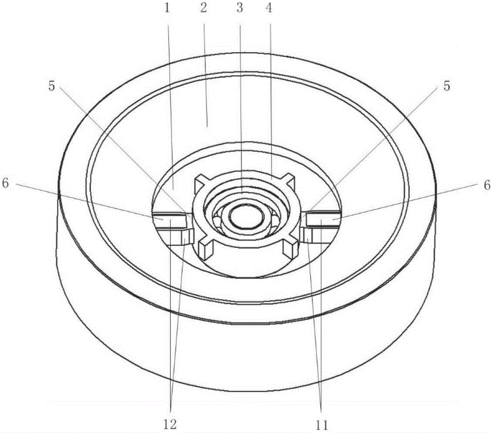
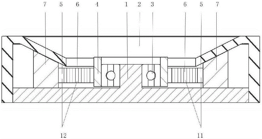
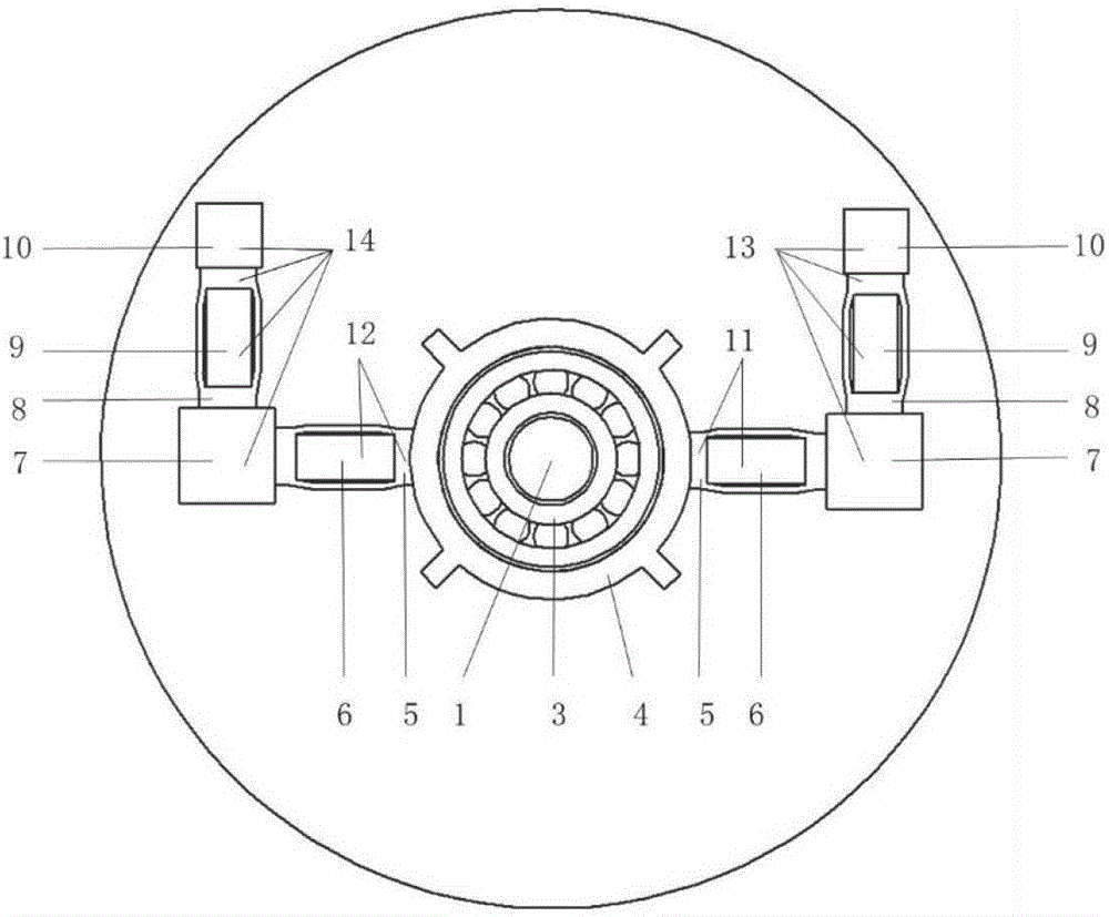
[0020] Such as Figure 1 to Figure 4 As shown, the clamp controllable disc-shaped rotary inertial piezoelectric actuator of the present invention includes a base 1, a clamp housing 2, a bearing 3, an output ring 4, a clockwise clamp mechanism 11, and a counterclockwise clamp mechanism 12 1. The clockwise driving mechanism 13 and the counterclockwise driving mechanism 14, the whole actuator structure is symmetrical; wherein the clamping shell 2 is obtained by turning an "M" shaped section with a certain thickness and cutting the central part to form a round hole, and the clamping shell 2 The internal thread is connected with the external thread on the circumferential side of the base 1; the clockwise clamping mechanism 11 and the counterclockwise clamping mechanism 12 both include a clamping rhombic ring 5 and a clamping piezoelectric ...


PUM


Abstract

The invention discloses a clamping controllable disc-shaped rotary type inertia piezoelectric actuator and an actuation method. The actuator is composed of a base, a clamping housing, a bearing, an output ring, clamping rhombic rings, clamping piezoelectric stacks, main movement blocks, mass blocks, driving rhombic rings and driving piezoelectric stacks, and the whole actuator is structurally symmetrical; the clamping rhombic rings and the driving rhombic rings are internally respectively in interference fit with the clamping piezoelectric stacks and the driving piezoelectric stacks, the mass blocks and the aforementioned parts are not in contact with the base, and mass centers are disposed in the same plane parallel to the base; and the output ring is connected with a fixation shaft at the center of the base through the bearing, the two clamping rhombic rings whose end surfaces are fixedly connected with the outer ring surface of the output ring are radially arranged at the two sides of the same diameter, axes of the clamping rhombic rings and the driving rhombic rings are vertical to each other, the two are connected through adjacent side surfaces of the main movement blocks placed on a plane of the base, the side surfaces of the mass blocks are fixedly connected with the driving rhombic rings, and other surfaces of the mass blocks are suspended above the base. The structure is novel, clamping is reliable, and bidirectional rotation can be realized.

Description

technical field [0001] The invention belongs to the technical field of inertial piezoelectric actuators, and in particular relates to a clamp-controllable disk-shaped rotary inertial piezoelectric actuator and an actuating method. Background technique [0002] Inertial piezoelectric actuator is a kind of mechanism that adopts asymmetrical driving signal, asymmetrical mechanical clamping structure or asymmetrical friction force as the control mode, and forms the driving mechanism through inertial impact motion. [0003] Compared with other types of piezoelectric drives, inertial piezoelectric actuators have the main advantages of simple structure, fast response, high resolution, large stroke, fast movement speed, and low cost. positioning accuracy. Therefore, inertial piezoelectric actuators are suitable for occasions that require high resolution and large strokes. At present, scientific and technological workers have successfully applied inertial piezoelectric actuators to...

Claims


Application Information

Patent Timeline
IPC IPC(8): H02N2/10H02N2/14
CPCH02N2/10H02N2/142
Inventor 邵妍徐明龙敬子建张丰
Owner XI AN JIAOTONG UNIV
Learn More