
Metering calibration device

A technology of calibration device and calibration block, which is applied in the direction of measurement device, force/torque/work measuring instrument calibration/test, instrument, etc. , Simple structure, easy to use effect

Pending Publication Date: 2020-11-27
HENAN PROVINCE INST OF METROLOGY
View PDF0 Cites 2 Cited by
  • Summary
  • Abstract
  • Description
  • Claims
  • Application Information

AI Technical Summary

Problems solved by technology

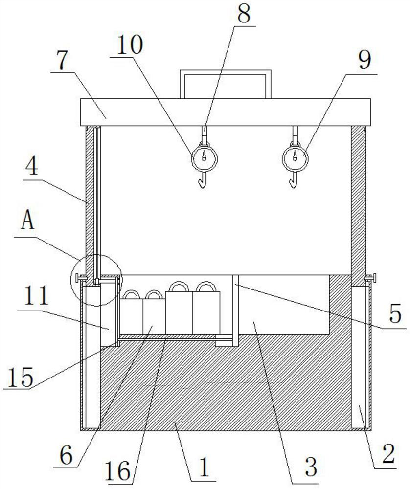
[0004] The purpose of the present invention is to solve the shortcomings of the measurement and calibration device, which are large in size, inconvenient to carry, and poor in flexibility of use, and propose a measurement and calibration device

Method used


Image

  • Metering calibration device
  • Metering calibration device
  • Metering calibration device

Examples


Embodiment 1

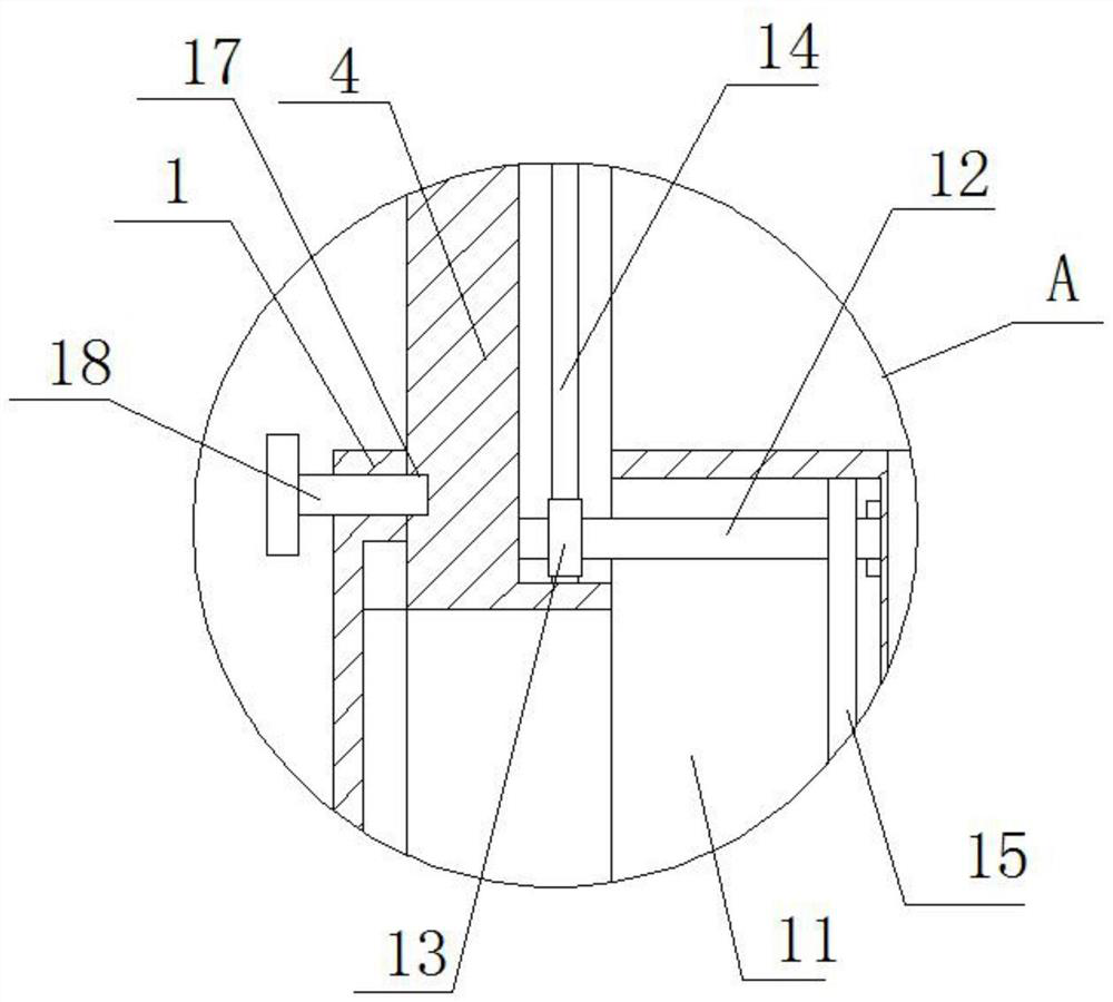
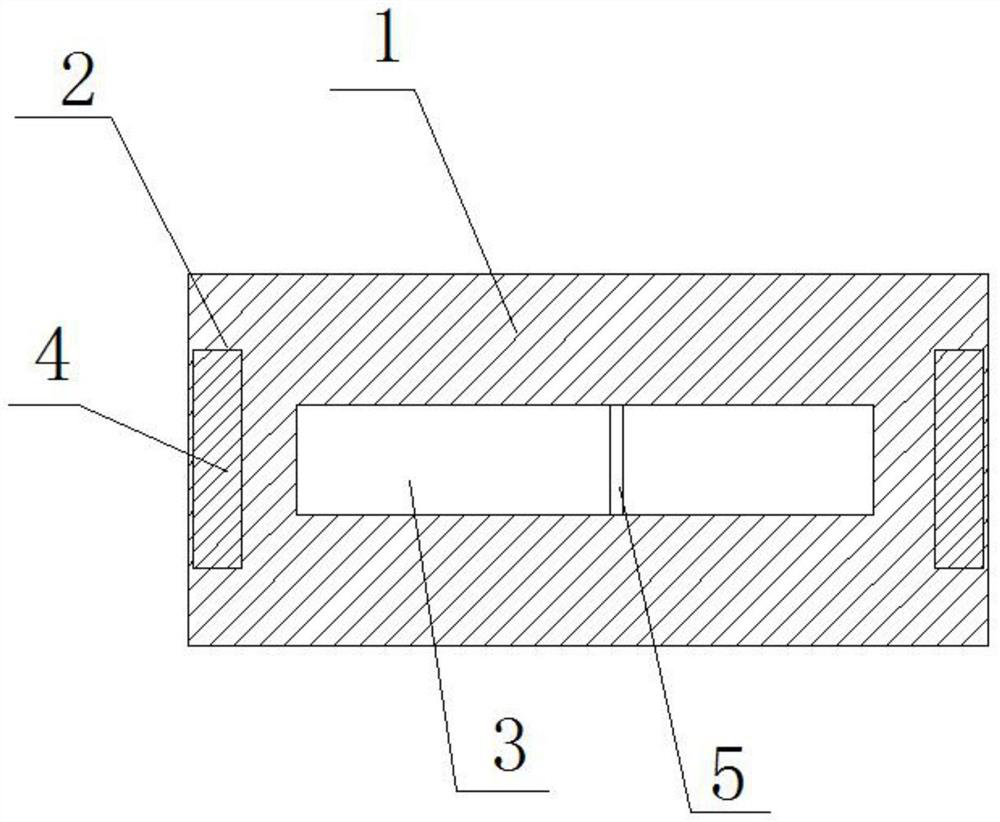
[0020] refer to Figure 1-3 , a measurement and calibration device, including a mounting base 1, the top of the mounting base 1 is provided with two slide grooves 2 and a placement groove 3, two sets of calibration blocks 6 are placed in the placement groove 3, and the top of the calibration block 6 is fixedly connected with Hanging ring, the lifting plate 4 is slidingly installed in the two chute 2, the same cover plate 7 is fixedly installed on the top of the two lifting plates 4, the top of the cover plate 7 is fixedly installed with a handle, and the bottom of the cover plate 7 is fixedly installed There are two fixed hooks 8, on which the dynamometer 9 to be calibrated and the standard dynamometer 10 are hung respectively, and two thread grooves 17 are provided on the sides of the two lifting plates 4 that are far away from each other, and the mounting base 1 Bolts 18 are threadedly installed on both sides of the body, and two bolts 18 are threadedly connected with corres...

Embodiment 2

[0026] refer to Figure 1-3 , a measurement and calibration device, including a mounting base 1, the top of the mounting base 1 is provided with two slide grooves 2 and a placement groove 3, two sets of calibration blocks 6 are placed in the placement groove 3, and the top of the calibration block 6 is fixedly connected with Hanging ring, the lifting plate 4 is slidably installed in the two chute 2, the top of the two lifting plates 4 is fixedly installed with the same cover plate 7 by welding, the top of the cover plate 7 is fixedly installed with a handle by welding, the cover plate 7 Two fixed hooks 8 are fixedly installed on the bottom by welding, and the dynamometer 9 to be calibrated and the standard dynamometer 10 are respectively hung on the two fixed hooks 8, and two screw threads are provided on the sides of the two lifting plates 4 that are far away from each other. Bolts 18 are threadedly installed on both sides of the mounting base 1 , and two bolts 18 are threade...


PUM


Abstract

The invention belongs to the technical field of metering calibration, in particular to a metering calibration device, and aims to solve the problems that an existing metering calibration device is large in size, inconvenient to carry and low in the using flexibility. Proposed now is the following scheme, the device comprises a mounting base, two sliding grooves and a containing groove are formed in the top of the mounting base. Two groups of calibration blocks are placed in the containing groove; the top of each calibration block is fixedly connected with a hanging ring; lifting plates are mounted in the two sliding grooves in a sliding manner; the same cover plate is fixedly mounted at the tops of the two lifting plates; a handle is fixedly mounted at the top of the cover plate; two fixing hooks are fixedly installed at the bottom of the cover plate, a dynamometer to be calibrated and a standard dynamometer are hung on the two fixing hooks respectively, and two threaded grooves are formed in the sides, away from each other, of the two lifting plates, so that the two lifting plates are contracted conveniently, the occupied space is reduced, and the device is convenient to carry, simple in structure and convenient to use.

Description

technical field [0001] The invention relates to the technical field of measurement calibration, in particular to a measurement calibration device. Background technique [0002] During the long-term use of the spring dynamometer, the spring will be deformed, which will make the measurement results of the dynamometer inaccurate. At this time, it needs to be calibrated. [0003] The existing metering and calibrating devices are bulky, not easy to carry, and have poor flexibility in use. Therefore, we propose a metering and calibrating device to solve the above problems. Contents of the invention [0004] The purpose of the present invention is to solve the shortcomings of the measurement and calibration device, such as large volume, inconvenient to carry, and poor flexibility of use, and propose a measurement and calibration device. [0005] In order to achieve the above object, the present invention adopts the following technical solutions: [0006] A metering and calibrat...

Claims


Application Information

Patent Timeline
IPC IPC(8): G01L25/00
CPCG01L25/00
Inventor 张书伟贾会李会娜武红芳许建军杨宇刘斌杰李琛
Owner HENAN PROVINCE INST OF METROLOGY
Learn More