A cable bridge that can realize the function of cable partition

A cable tray and function technology, applied in the direction of electrical components, etc., can solve the problems of inconvenient cable fixing, inconvenient adjustment of cable tray, inconvenient cable maintenance and replacement, etc., to achieve the effect of easy maintenance, replacement and easy fixation

Active Publication Date: 2021-11-05
江苏中顺电气有限公司
View PDF18 Cites 0 Cited by
  • Summary
  • Abstract
  • Description
  • Claims
  • Application Information

AI Technical Summary

Problems solved by technology

[0002] A cable is a kind of electrical energy or signal transmission device, usually composed of several or several groups of wires. The use environment of cables is roughly divided into aerial cables and underground cables, while aerial cables need to use cable bridges to overhead cables, cable trays It is divided into trough type, tray type, ladder frame type, grid type and other structures. It is composed of brackets, supporting arms and installation accessories. The bridge frame in the building can be erected independently or laid on various buildings and pipe gallery supports. It should reflect the characteristics of simple structure, beautiful appearance, flexible configuration and convenient maintenance. All parts need to be galvanized. If the bridge frame installed in the open air outside the building is near the sea or belongs to the corrosion area, the material must be anti-corrosion, The physical characteristics of moisture resistance, good adhesion, and high impact strength. In engineering design, the layout of the bridge frame should be comprehensively compared based on factors such as economic rationality, technical feasibility, and operational safety to determine the best plan. To meet the requirements of construction, installation, maintenance and cable laying, the traditional cable tray cannot partition the cables, and it is not convenient to adjust the position of the cable tray after fixing, it is inconvenient to maintain and replace the cables, and it is not convenient to fix the cables, so it is proposed A cable tray that can realize the function of cable partition is imperative

Method used


Image

  • A cable bridge that can realize the function of cable partition
  • A cable bridge that can realize the function of cable partition
  • A cable bridge that can realize the function of cable partition

Examples


Embodiment Construction

[0026] The following will clearly and completely describe the technical solutions in the embodiments of the present invention with reference to the accompanying drawings in the embodiments of the present invention. Obviously, the described embodiments are only some, not all, embodiments of the present invention. Based on the embodiments of the present invention, all other embodiments obtained by persons of ordinary skill in the art without making creative efforts belong to the protection scope of the present invention.

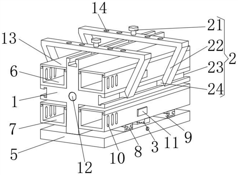
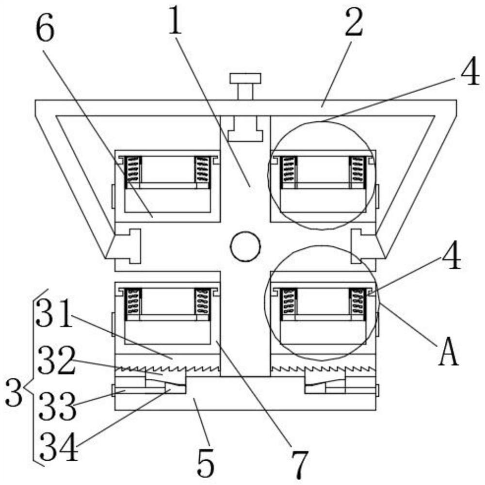
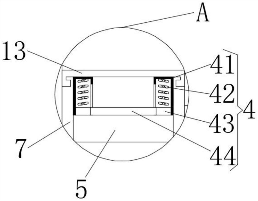
[0027] see Figure 1-3 , the present invention provides a technical solution: a cable bridge that can realize the function of cable partition, including a cross fixing frame 1, an installation structure 2, a limiting structure 3 and a fixing structure 4;

[0028] Cross fixing frame 1: fixed wire groove 6 is arranged symmetrically in the middle left and right, bottom plate 5 is installed on the lower surface of cross fixing frame 1, and chute plate 9 is arrange...


PUM


Abstract

The invention discloses a cable bridge that can realize the function of cable division, including a cross fixing frame, an installation structure, a limit structure and a fixing structure; The bottom plate is installed, and the left and right ends of the upper surface of the bottom plate are symmetrically provided with chute plates. The inside of the chute plate is slidably connected with slide bars, and the upper surfaces of the two corresponding slide bars are fixed to the lower surface of the movable wire slot. Connection, the front-end opposite outer sides of the two fixed wire slots and the front-end opposite outer sides of the two movable wire slots are uniformly provided with connection holes; installation structure: front and rear symmetrically arranged on the upper end of the cross bracket; the cable that can realize the cable partition function The cable tray can be used to partition the cables, which is convenient for adjusting the position of the cable tray, for maintaining and replacing the cables inside the movable trunking, and for fixing the cables.

Description

technical field [0001] The invention relates to the technical field of overhead cables, in particular to a cable bridge that can realize the function of cable division. Background technique [0002] A cable is a kind of electrical energy or signal transmission device, usually composed of several or several groups of wires. The use environment of cables is roughly divided into aerial cables and underground cables, while aerial cables need to use cable bridges to overhead cables, cable trays It is divided into trough type, tray type, ladder frame type, grid type and other structures. It is composed of brackets, supporting arms and installation accessories. The bridge frame in the building can be erected independently or laid on various buildings and pipe gallery supports. It should reflect the characteristics of simple structure, beautiful appearance, flexible configuration and convenient maintenance. All parts need to be galvanized. If the bridge frame installed in the open a...

Claims


Application Information

Patent Timeline
Patent Type & Authority Patents(China)
IPC IPC(8): H02G3/04H02G3/34
CPCH02G3/045H02G3/34
Inventor 刘洋
Owner 江苏中顺电气有限公司
Why Eureka
Try Eureka