A mountain guardrail structure with guiding force
A technology of guardrail structure and guiding force, applied in the direction of springs/shock absorbers, roads, buildings, etc., can solve the problems of inability to reduce the impact force, damage to cars and guardrails, danger, etc., and achieve the effect of reducing the impact force
- Summary
- Abstract
- Description
- Claims
- Application Information
AI Technical Summary
Problems solved by technology
Method used
Image
Examples
Embodiment 1
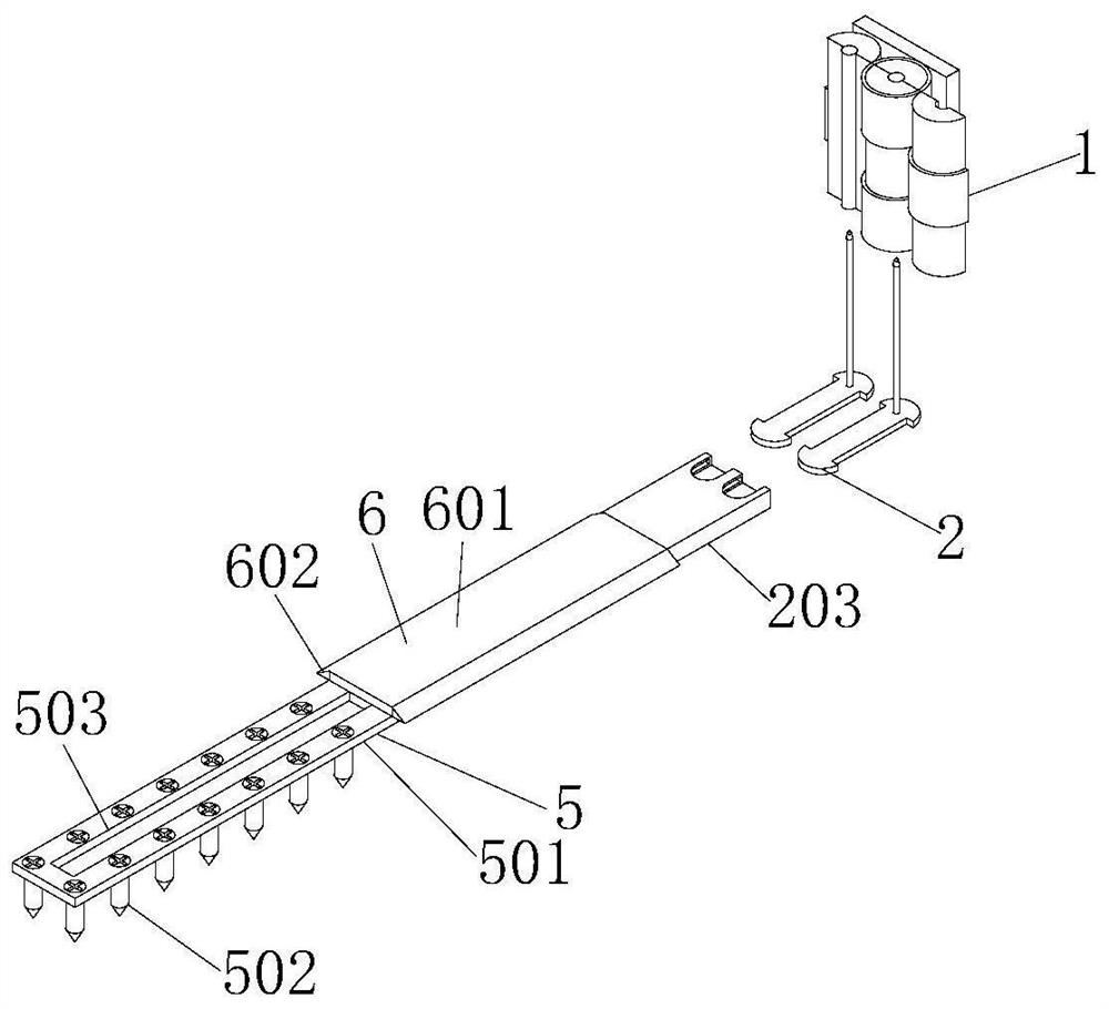
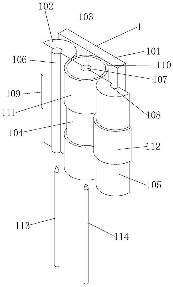
[0037] Example 1: Please refer to figure 2 , the present invention provides a technical solution: a mountain guardrail structure with guiding force, including a guardrail post 1, the guardrail post 1 includes a baffle 101, a rotating post 102 and a rotating post 2 103, and the front of the baffle 101 is provided with a rotating The first column 102, the second column 103, the third column 104 and the fourth column 105, the middle part of the front surface of the first rotating column 102 is fixedly connected with the central column 106, and the middle part of the rear surface of the first rotating column 102 is provided with an airbag belt 109, One end of the airbag belt 109 is fixedly connected to the rotating column 102, and the other end of the airbag belt 109 is fixedly connected to the left end of the rotating column 2 103, and the airbag belt 109 is attached to the rear side wall of the rotating column 102;
[0038] The right side of rotating column one 102 is provided ...
Embodiment 2
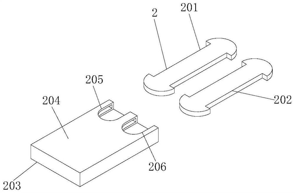
[0045] Example 2: Please refer to Figure 1-Figure 5 as well as Figure 7 and Figure 8 , on the basis of embodiment one: a kind of mountain guardrail structure with guiding force, the below of guardrail post 1 is provided with moving device 2, and moving device 2 comprises moving plate one 201, moving plate two 202 and moving box 203, and moving plate The front end and rear end of the first 201 and the second movable plate 202 are semicircular structures, the rear surfaces of the first movable plate 201 and the second movable plate 202 are fixedly connected with the baffle plate 101, and the rear end of the upper surface of the first movable plate 201 is fixedly connected and rotates Column 1 113, the rear end of the upper surface of moving plate 2 202 is fixedly connected to rotating column 2 114, the front of moving plate 1 201 and moving plate 2 202 is provided with moving box 203, and the upper surface of moving box 203 is fixedly connected with upper cover plate 204, T...
Embodiment 3
[0051] Example 3: Please refer to Figure 3-Figure 6 , on the basis of embodiment two, a kind of mountain guardrail structure with guiding force, the right side of drum three 307 is provided with deceleration device 4, deceleration device 4 comprises deceleration table 401, arc mouth 402 and cushion one 403, deceleration Platform 401 is at the right rear position of drum three 307, and the lower surface of deceleration table 401 is fixedly connected on the base plate 308, and deceleration table 401 is provided with arc mouth 402 at the end close to drum three 307, and arc mouth 402 and drum three 307 is adapted, the inner wall of the arc opening 402 is fixedly connected with a cushion one 403, the middle part of the right surface of the drum three 307 is fixedly connected with a cylinder 404, and the right side of the drum three 307 is provided with an arc plate 405, the number of arc plates 405 The two arc plates 405 are arranged symmetrically with the cylinder 404 as the cen...
PUM
 Abstract
Description
Claims
Application Information
 - R&D
- Intellectual Property
- Life Sciences
- Materials
- Tech Scout
- Unparalleled Data Quality
- Higher Quality Content
- 60% Fewer Hallucinations
Browse by: Latest US Patents, China's latest patents, Technical Efficacy Thesaurus, Application Domain, Technology Topic, Popular Technical Reports.
© 2025 PatSnap. All rights reserved.Legal|Privacy policy|Modern Slavery Act Transparency Statement|Sitemap|About US| Contact US: help@patsnap.com


