Automatic door remote control system

A remote control system and automatic door technology, applied in door/window accessories, power control mechanism, anti-theft alarm mechanical start, etc., can solve the problems of difficult speed control, low energy utilization efficiency, and being opened by people, so as to improve the accuracy rate Effect

Inactive Publication Date: 2020-12-01
广州高腾科技有限公司
View PDF6 Cites 1 Cited by
  • Summary
  • Abstract
  • Description
  • Claims
  • Application Information

AI Technical Summary

Problems solved by technology

At the beginning, it was difficult to control the speed of the motor with the power supply for the building, so we had to control the speed of the oil pressure and air pressure, but the efficiency of energy utilization was very low. However, with the development of electrical control technology, the electrical control technology has matured. Electric automatic doors that directly control the motor are gradually becoming mainstream
[0003] In today's society, people usually need to go to work, and there is no guarantee that there are always people at home. If the family does not have a key when we go to work, how can we open the door? This is a problem that many, many people have encountered. Then when we go out or go to work, the door of our home is opened by someone, and it is a stranger. How can we know this? How can we prevent strangers from opening our home? The door, this is a big problem that needs to be solved

Method used


Image

  • Automatic door remote control system
  • Automatic door remote control system
  • Automatic door remote control system

Examples


Embodiment Construction

[0047] The following will clearly and completely describe the technical solutions in the embodiments of the present invention with reference to the accompanying drawings in the embodiments of the present invention. Obviously, the described embodiments are only some, not all, embodiments of the present invention. Based on the embodiments of the present invention, all other embodiments obtained by persons of ordinary skill in the art without making creative efforts belong to the protection scope of the present invention.

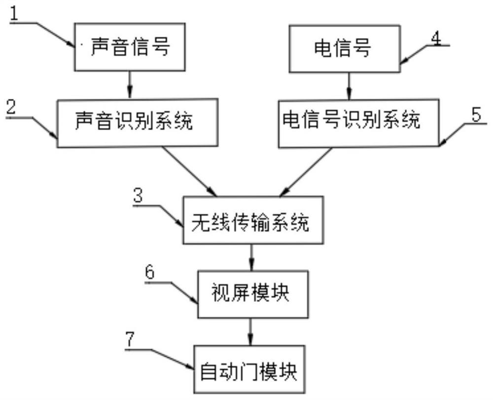
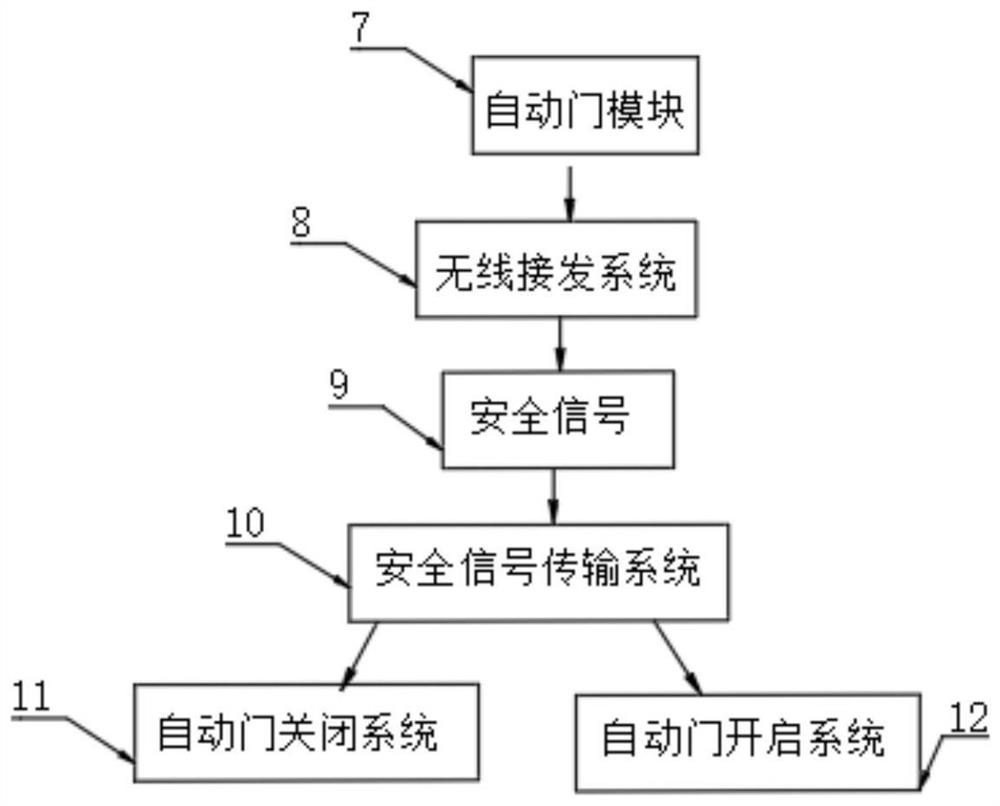
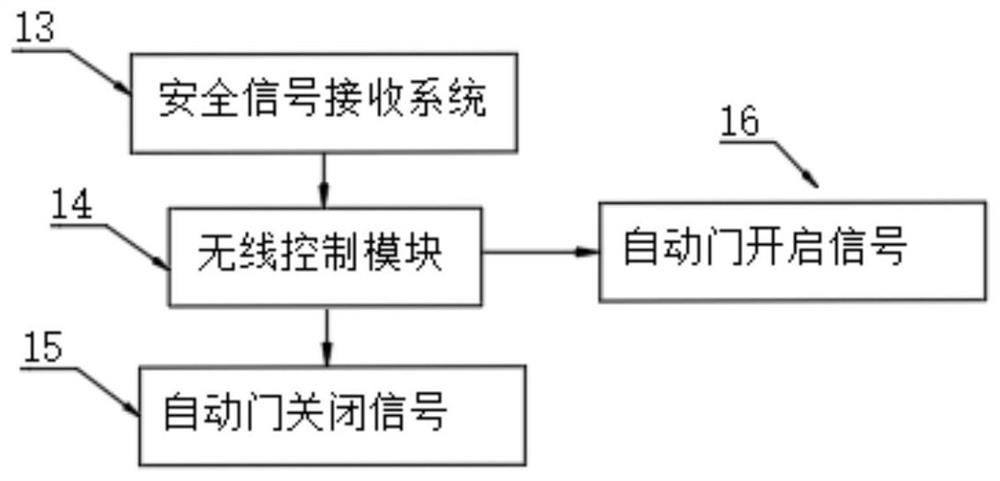
[0048] as attached Figure 1-5 A remote control system for an automatic door is shown, including a voice recognition system 2, a wireless transmission system 3, an automatic door module 7, and a wireless control module 14. The input terminal of the voice recognition system 2 is connected to the voice signal 1, and the voice recognition system 2 outputs The terminal is connected with the input terminal of the wireless transmission system 3, the electrical signal ...


PUM


Abstract

The invention discloses an automatic door remote control system, and particularly relates to the field of remote control. The system comprises a voice recognition system, a wireless transmission system, an automatic door module and a wireless control module, the input end of the voice recognition system is connected with a voice signal; the output end of the voice recognition system is connected with the input end of the wireless transmission system; the electric signal is connected with the input end of an electric signal recognition system; the output end of the electric signal recognition system is connected with the input end of the wireless transmission system; the output end of the wireless transmission system is connected with the input end of a view screen module; the output end ofthe view screen module is connected with the input end of the automatic door module; the automatic door remote control system is added and used for monitoring the operation condition of a door of a house, and a low-electric-quantity electric shock defense system is added so that a door can be opened without a key when no person is at home, a good defense means can be provided, and strangers are prevented from entering the house of an owner.

Description

technical field [0001] The invention relates to the technical field of remote control, and more specifically, the invention relates to a remote control system for an automatic door. Background technique [0002] Automatic doors began to be used in buildings after the 20th century. In the late 1920s, with the opening of supermarkets in the United States, automatic doors began to be used. In 1930, Stanley of the United States launched the world's first automatic door (this historical material was recorded in the New York Times). By 1962, electric doors had begun to appear, and with the construction of cities, the field of automatic door technology increased every year. At the beginning, it was difficult to control the speed of the motor with the power supply for the building, so we had to control the speed of the oil pressure and air pressure, but the efficiency of energy utilization was very low. However, with the development of electrical control technology, the electrical...

Claims


Application Information

Patent Timeline
Patent Type & Authority Applications(China)
IPC IPC(8): E05F15/77F41H13/00G08B13/08G08B15/00
CPCE05Y2900/132E05F15/77F41H13/0031G08B13/08G08B15/005
Inventor 孙玉林
Owner 广州高腾科技有限公司
Why Eureka
Try Eureka