Actuator for hydraulic valve and hydraulic valve

A technology for actuators and hydraulic valves, applied in the field of hydraulic valves and actuators, can solve problems such as leakage of lateral force, improvement, and adverse effects on adjustment quality, and achieve the effect of simple cost and saving coating consumption

Inactive Publication Date: 2020-12-01
ECO HLDG 1 GMBH
View PDF9 Cites 0 Cited by
  • Summary
  • Abstract
  • Description
  • Claims
  • Application Information

AI Technical Summary

Problems solved by technology

Although a high degree of robustness can be achieved with large play in the parts to be moved, this has a negative effect on the adjustment quality and the generated magnetic forces
Furthermore, this large gap leads to leakage and increased lateral forces acting on the magnet

Method used


Image

  • Actuator for hydraulic valve and hydraulic valve
  • Actuator for hydraulic valve and hydraulic valve

Examples


Embodiment Construction

[0028] In the figures, the same or the same type of parts are denoted by the same reference numerals. The drawings show examples only and are not to be construed as limiting.

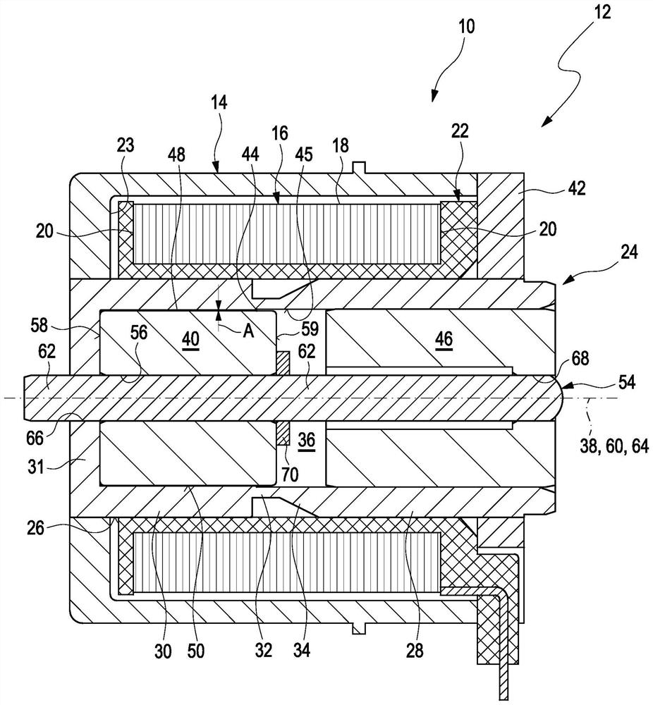
[0029] exist figure 1 The actuator 10 according to the invention of the hydraulic valve 12 according to the invention is shown in longitudinal section. Starting from the actuator 10, the hydraulic valve 12, which is not shown in detail among the components configured for hydraulic functions, also includes a control valve with a housing with hydraulic connections, the housing has An axially movable hydraulically permeable piston is accommodated axially displaceably in order to release and close a throughflow opening formed in the housing. The piston is positioned axially by means of the actuator 10 .

[0030]The actuator 10 comprises a magnetizable actuator housing 14 which surrounds the magnetic coil 16 on its outer circumference 18 and on at least one end face 20 of the magnetic coil. For reasons o...


PUM


Abstract

The invention relates to an actuator for a hydraulic valve, in particular a hydraulic transmission valve. The actuator has a magnetizable actuator housing (14) and a pole group (24). The actuator housing encloses a magnetic coil (16), the pole group (24) is arranged in a housing receiving opening (23) of the actuator housing (14), the pole group (24) comprises at least one pole core (28) and a pole tube (30), and an axially displaceably received armature (40) is arranged in an inner chamber (36) of the pole group (24). The aim of the invention is to reduce friction between the armature (40) and the pole group (24), an air gap (48) is formed completely between the peripheral surface (50) of the armature (40) and the inner surface (45) of the inner chamber (36), the air gap (48) being designed to create a constant distance (A) between the armature (40) and the pole group (24) over the circumference of the armature (40) in order to centrally support the armature (40) in the pole group (24). The invention also relates to a hydraulic valve (12).

Description

technical field [0001] The invention relates to an actuator for a hydraulic valve and to a hydraulic valve, in particular a hydraulic transmission valve of a motor vehicle. Background technique [0002] In order to be fail-safe even with relatively large transmission oil change intervals, in extreme cases over the so-called expected service life, the transmission valve must have a high degree of robustness. Although a high degree of robustness can be achieved with large play in the parts to be moved, this has a negative effect on the adjustment quality and the generated magnetic forces. Furthermore, this large gap leads to leakage and increased lateral forces acting on the magnet. [0003] A hydraulic valve is known from DE 10 2011 053 023 A1 which, in addition to high control qualities, also has high robustness. The high robustness is achieved by the fact that dirt particles in the operating medium do not cause the transmission valve to jam, since the armature can exert s...

Claims


Application Information

Patent Timeline
Patent Type & Authority Applications(China)
IPC IPC(8): F16K31/06H01F7/121H01F7/126H01F7/16
CPCF16K31/0675H01F7/121H01F7/126H01F7/16H01F7/1607H01F7/081H01F2007/085
Inventor 迪特·迈什哈特莫特·韦伯
Owner ECO HLDG 1 GMBH
Why Eureka
Try Eureka