Electronic product environment test system with sample protection function
A protection function and technology for electronic products, applied in the field of electronic product environmental test systems, can solve problems such as sample short circuit, current rise, damaged samples, etc., and achieve the effects of improving test efficiency, convenient setting, and avoiding damage
- Summary
- Abstract
- Description
- Claims
- Application Information
AI Technical Summary
Problems solved by technology
Method used
Image
Examples
Embodiment 1
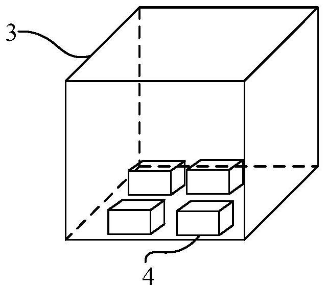
[0023] In the existing environmental test, it is required that the sample should not be short-circuited due to the increase of the voltage or current value of the external power supply, or the increase of the current required by the sample in a certain experimental environment, and the protection from the outside world should be carried out. The samples are disconnected in time to ensure that the samples do not appear damaged. Such as figure 1 As shown, the present embodiment provides an electronic product environmental testing system with a sample protection function, including a DC power supply 1, a sample protection device 2 and an environmental test chamber 3, and the sample protection device 2 is respectively connected to the DC power supply 1 and installed in the environmental test chamber Sample 4 in 3, sample protection device 2 includes a DC power input terminal, a voltage and current limiting unit, and a power output terminal connected in sequence, the DC power input...
Embodiment 2
[0027] In the electronic product environmental test system with sample protection function provided by this embodiment, such as figure 2 As shown, the voltage limiting and current limiting unit also includes a first reactor L 1 , the second reactor L 2 , the first capacitance C 1 , the second capacitance C 2 and Zener diode D, the first reactor L 1 One end is connected to the fuse FU, the other end is connected to one terminal of the power output terminal, the fuse FU is connected to one terminal of the DC power input terminal, and the second reactor L 2 One end is connected to the other terminal of the DC power input terminal, the other end is connected to the other terminal of the power output terminal, and the first capacitor C 1 , Zener diode D and the second capacitor C 2 Connect them in parallel with the output terminals of the power supply in turn.
[0028] In this embodiment, the first reactor L 1 and the second reactor L 2 Both are magnetic core reactors or i...
PUM
 Abstract
Description
Claims
Application Information
 - R&D
- Intellectual Property
- Life Sciences
- Materials
- Tech Scout
- Unparalleled Data Quality
- Higher Quality Content
- 60% Fewer Hallucinations
Browse by: Latest US Patents, China's latest patents, Technical Efficacy Thesaurus, Application Domain, Technology Topic, Popular Technical Reports.
© 2025 PatSnap. All rights reserved.Legal|Privacy policy|Modern Slavery Act Transparency Statement|Sitemap|About US| Contact US: help@patsnap.com


