
A method for forming a groove

A trench and trench isolation technology, applied in radiation control devices, semiconductor devices, electrical components, etc., can solve the problems of polysilicon residue in the logic area and pixel area, polysilicon over-etching in the logic area, etc.

Active Publication Date: 2021-02-05
晶芯成(北京)科技有限公司
View PDF6 Cites 0 Cited by
  • Summary
  • Abstract
  • Description
  • Claims
  • Application Information

AI Technical Summary

Problems solved by technology

[0004] The purpose of the present invention is to provide a trench formation method to solve the problem of polysilicon residue in the logic region and the pixel region, or the problem of polysilicon over-etching in the logic region

Method used


Image

  • A method for forming a groove
  • A method for forming a groove
  • A method for forming a groove

Examples


Embodiment Construction

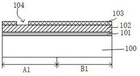
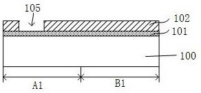
[0030] A method for forming a trench proposed by the present invention will be further described in detail below with reference to the accompanying drawings and specific embodiments. The advantages and features of the present invention will become clearer from the following description. It should be noted that all the drawings are in a very simplified form and use imprecise scales, and are only used to facilitate and clearly assist the purpose of illustrating the embodiments of the present invention.

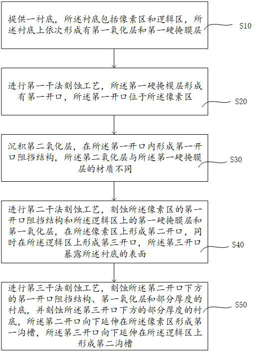
[0031] figure 1 It is a flowchart of a method for forming a groove according to an embodiment of the present invention. like figure 1 As shown, the present invention provides a method for forming a groove, comprising:

[0032] Step S10, providing a substrate, the substrate includes a pixel region and a logic region, and a first oxide layer and a first hard mask layer are sequentially formed on the substrate;

[0033] Step S20, performing a first dry etching process, the firs...


PUM

PropertyMeasurementUnit
thicknessaaaaaaaaaa

Abstract

The invention provides a method for forming a groove. The method comprises the following steps of providing a substrate, wherein the substrate comprises a pixel region and a logic region, and a firstoxide layer and a first hard mask layer are sequentially formed on the substrate; carrying out a first dry etching process, forming a first opening in the first hard mask layer, and enabling the firstopening to be located in the pixel region; depositing a second oxide layer, and forming a first opening blocking structure in the first opening; and performing a second dry etching process and a third dry etching process to form a first trench of the pixel region and a second trench of the logic region with different depths. According to the invention, etching selection ratios of the first opening blocking structure, the first oxide layer, the first mask layer and the substrate are different through the second dry etching process and the third dry etching process so as to form the pixel region first groove and the logic region second groove with different depth differences.

Description

technical field [0001] The invention relates to the technical field of semiconductors, in particular to a method for forming a trench. Background technique [0002] Image sensors usually include a logic region and a pixel region. In the existing STI (shallow trench isolation) process, different STI formation methods are used in the logic region and the pixel region, wherein the STI (shallow trench isolation) of the pixel region The isolation) depth is usually shallow to avoid the impact of dry etch residual plasma on the photoelectric conversion performance of the pixel area, while the STI in the logic area needs to be etched twice to reach a deeper depth. Specifically, first, the logic area and the pixel area are etched through the first dry etching process to obtain two STI trenches of the first depth; The STI trench of the first depth is etched to obtain the STI trench of the second depth (also called STI extended trench or deep trench isolation); then, in the pixel area...

Claims


Application Information

Patent Timeline
Patent Type & Authority Patents(China)
IPC IPC(8): H01L21/762H01L27/146
CPCH01L21/76229H01L27/14683
Inventor 陶磊王厚有冯永波刘西域
Owner 晶芯成(北京)科技有限公司
Learn More