
UPS bypass driving unit and UPS bypass driving system

A drive unit and drive system technology, applied in electrical components, circuit devices, emergency power supply arrangements, etc., can solve problems such as load failure, data loss, and inability to meet the actual use requirements of UPS power supply uninterruptible power supply.

Active Publication Date: 2020-12-01
KEHUA DATA CO LTD +1
View PDF9 Cites 0 Cited by
  • Summary
  • Abstract
  • Description
  • Claims
  • Application Information

AI Technical Summary

Problems solved by technology

However, if the DSP control module has abnormal conditions such as abnormal power supply or abnormal operation, the DSP control module cannot effectively control the bypass switch action, which prolongs the switching time of the bypass output state, resulting in power failure of the load in time , it is easy to cause problems such as load failure or data loss, which cannot meet the actual use requirements of UPS power supply for uninterrupted power supply

Method used


Image

  • UPS bypass driving unit and UPS bypass driving system
  • UPS bypass driving unit and UPS bypass driving system
  • UPS bypass driving unit and UPS bypass driving system

Examples


Embodiment Construction

[0054] The following will clearly and completely describe the technical solutions in the embodiments of the present invention with reference to the drawings in the embodiments of the present invention. Obviously, the described embodiments are preferred embodiments of the invention and should not be seen as excluding other embodiments. Based on the embodiments of the present invention, all other embodiments obtained by persons of ordinary skill in the art without creative efforts fall within the protection scope of the present invention.

[0055] In the claims, description and above-mentioned drawings of the present invention, unless otherwise clearly defined, the terms "first", "second" or "third" are used to distinguish different objects, not for Describe a specific order.

[0056] In the claims, specification and above-mentioned drawings of the present invention, unless otherwise clearly defined, for orientation words, such as using the terms "center", "transverse", "longit...


PUM


Abstract

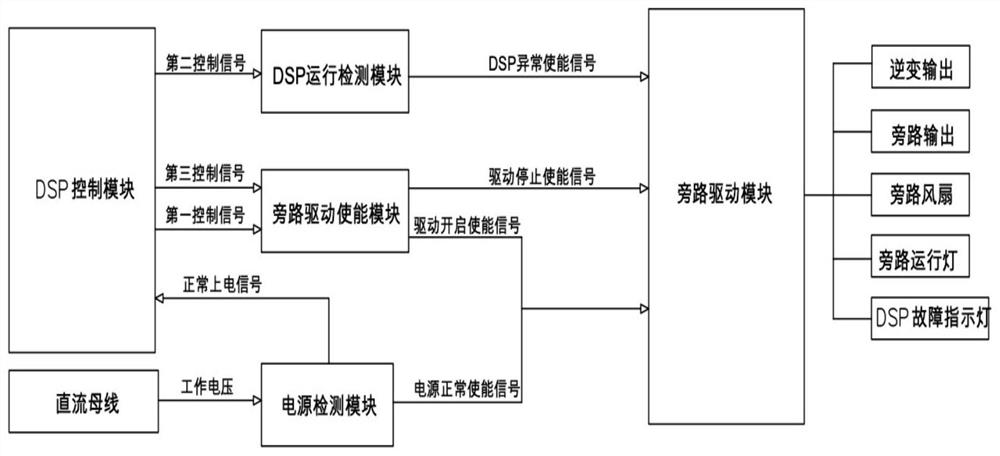
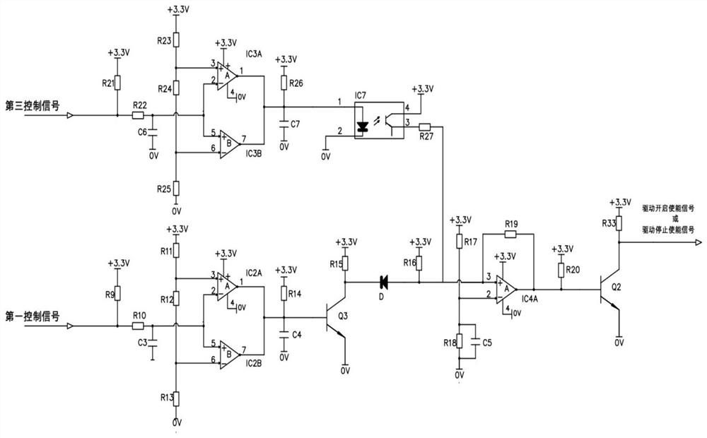
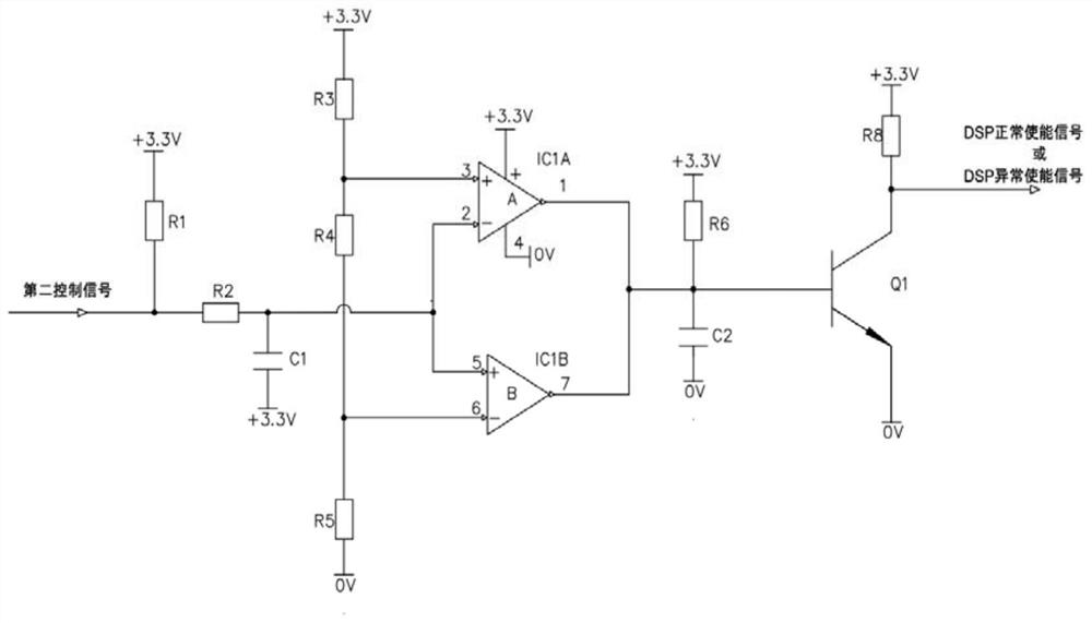
The invention discloses a UPS bypass driving unit, which comprises a DSP control module, a bypass driving enabling module, a DSP operation detection module and a bypass driving module, wherein the DSPcontrol module is used for sending a first control signal to the bypass driving enabling module and sending a second control signal to the DSP operation detection module; the bypass driving enablingmodule is used for sending a driving starting enabling signal to the bypass driving module when receiving the first control signal; the DSP operation detection module is used for sending a DSP abnormal enabling signal to the bypass driving module when detecting that the second control signal is abnormal; and the bypass driving module is used for forming a driving signal for starting bypass outputand stopping inversion output at the output end of the bypass driving module when receiving the driving starting enabling signal and the DSP abnormal enabling signal. The invention further discloses aUPS bypass driving system. The UPS bypass driving system comprises more than two UPS bypass driving units and a parallel operation switch control module. The UPS bypass driving unit is used for stably switching to a bypass output state in case of an operation fault so as to reliably supply power.

Description

technical field [0001] The invention relates to the technical field of integrated electronic circuits, in particular to a UPS bypass drive unit and a UPS bypass drive system. Background technique [0002] The existing UPS power supply generally includes a main circuit connected in series between the mains and the load and a bypass connected in parallel with the main circuit. Voltage constant frequency circuit, which is mainly used to charge the battery by the mains, and then provide a stable and uninterrupted power supply for the load by the battery after inverter; the bypass is mainly used when the main circuit fails or the load is overloaded The mains and the load are connected downwards, so that the mains can directly supply power to the load, thereby ensuring reliable power supply of the UPS power supply. [0003] The UPS power supply usually sets the DSP control module to realize the closure of the digital automatic control bypass switch, which is used to switch from t...

Claims


Application Information

Patent Timeline
IPC IPC(8): H02J9/06
CPCH02J9/062
Inventor 许永志江东升陈威龙陈培钦
Owner KEHUA DATA CO LTD
Learn More