
Assembly equipment with lighting structure for variable-speed motor

A lighting structure, variable speed motor technology, applied in lighting and heating equipment, lighting devices, fixed lighting devices, etc., can solve the problems of unable to move the assembly table, unable to limit the pressure plate, affecting the installation of the stator, etc., to achieve convenient use and improve brightness , the effect of uniform distribution

Inactive Publication Date: 2020-12-01
重庆信易源智能科技有限公司
View PDF0 Cites 2 Cited by
  • Summary
  • Abstract
  • Description
  • Claims
  • Application Information

AI Technical Summary

Problems solved by technology

[0004] The object of the present invention is to provide an assembly equipment with lighting structure for variable speed motors, so as to solve the problem that the existing assembly equipment for variable speed motors proposed in the above background technology generally does not have a specific lighting structure, and mostly adopts the way of indoor overall lighting, It is inconvenient to adjust the position of the lighting lamp, it is impossible to improve the brightness of a local area during assembly, and it is impossible to move and rotate the position of the assembly table, which is not flexible enough, and it is impossible to limit the position of the pressure plate when the stator is pressed and installed, which may The problem that the inclination affects the installation of the stator

Method used


Image

  • Assembly equipment with lighting structure for variable-speed motor
  • Assembly equipment with lighting structure for variable-speed motor
  • Assembly equipment with lighting structure for variable-speed motor

Examples


Embodiment Construction

[0028] The technical solutions in the embodiments of the present invention will be clearly and completely described below in conjunction with the accompanying drawings in the embodiments of the present invention. Obviously, the described embodiments are only some of the embodiments of the present invention, not all of them. Based on The embodiments of the present invention and all other embodiments obtained by persons of ordinary skill in the art without making creative efforts belong to the protection scope of the present invention.

[0029] In the description of the present invention, unless otherwise stated, the meaning of "plurality" is two or more; the terms "upper", "lower", "left", "right", "inner", "outer" , "front end", "rear end", "head", "tail", etc. indicate the orientation or positional relationship based on the orientation or positional relationship shown in the drawings, and are only for the convenience of describing the present invention and simplifying the desc...


PUM


Abstract

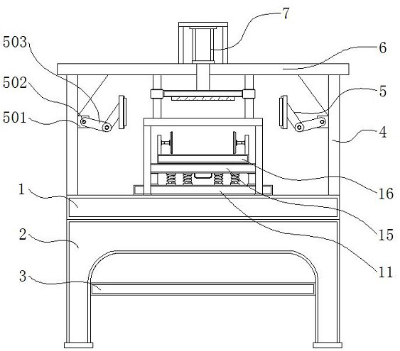
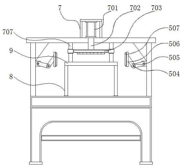
The invention discloses assembly equipment with a lighting structure for a variable-speed motor, and relates to the technical field of variable speed motors. The equipment comprises a supporting table, a lighting mechanism, a movable base and an assembling table. A supporting frame is fixed to the lower portion of the supporting table. A storage plate is mounted in the middle of the supporting frame; a fixing column is welded to the outer side of the upper portion of the supporting table; a top plate is fixed above the fixing column; the lighting mechanism is mounted on the inner side of the fixing column; a pressing mechanism is mounted above the top plate; and supporting rod plates are fixed to the four sides of the upper portion of the supporting table. The beneficial effects of the equipment are that the lighting mechanism is arranged, so that illumination can be conveniently provided for the assembling table, and the brightness is conveniently improved; and two sets of symmetrically-distributed illuminating lamps enable the illuminating range to be evenly distributed, and the positions of a mounting plate and the illuminating lamps can be movably adjusted conveniently througha second connecting rod, a second rotating shaft, a first connecting rod and a first rotating shaft, so the illuminating brightness of a local area can be flexibly adjusted conveniently, and use is more convenient and faster.

Description

technical field [0001] The invention relates to the technical field of variable speed motors, in particular to an assembly device with lighting structure for variable speed motors. Background technique [0002] A variable speed motor is a rotary machine that converts electrical energy into mechanical energy. It mainly includes an electromagnet winding or a distributed stator winding for generating a magnetic field and a rotating armature or rotor, with current passing through its wires and receiving a magnetic field. Some types of these machines can be used as motors or generators, and assembly equipment is required in the assembly process of variable speed motors. [0003] The existing assembly equipment for variable speed motors generally does not have a specific lighting structure, and mostly adopts the method of indoor overall lighting, which is inconvenient to adjust the position of the lighting lamp, cannot improve the brightness of a local area during assembly, and ca...

Claims


Application Information

Patent Timeline
Patent Type & Authority Applications(China)
IPC IPC(8): H02K15/02F21S8/08F21V21/26
CPCF21S8/08F21V21/26H02K15/02
Inventor 谢晶晶张万娟
Owner 重庆信易源智能科技有限公司
Learn More