Method and device for determining cell activation delay

A cell activation and cell technology, applied in the field of communications, to achieve the effect of improving the success rate of activation

Active Publication Date: 2020-12-01
HUAWEI TECH CO LTD
View PDF6 Cites 4 Cited by
  • Summary
  • Abstract
  • Description
  • Claims
  • Application Information

AI Technical Summary

Problems solved by technology

However, as terminal equipment and network equipment have higher and higher requirements on the activation

Method used


Image

  • Method and device for determining cell activation delay
  • Method and device for determining cell activation delay
  • Method and device for determining cell activation delay

Examples


Embodiment Construction

[0063]The technical solution in this application will be described below with reference to the accompanying drawings.

[0064] The terms involved in this application are described in detail below:

[0065] 1. Beam:

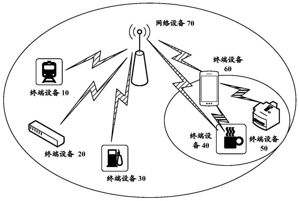
[0066] A beam is a communication resource, and different beams can be regarded as different communication resources. Different beams can send the same information, or different information. A beam may correspond to at least one of time domain resources, space resources and frequency domain resources.

[0067] Optionally, multiple beams with the same or type of communication characteristics may be regarded as one beam, and one beam may include one or more antenna ports for transmitting data channels, control channels, and sounding signals. For example, the transmitting beam may refer to the distribution of signal strength formed in different directions in space after the signal is transmitted by the antenna; the receiving beam may refer to the distribution of si...


PUM


Abstract

The invention provides a method and a device for determining cell activation time delay. The method comprises the following steps that: terminal equipment or network equipment can respectively determine activation time delay corresponding to a to-be-activated cell according to the fact that downlink spatial filtering of a downlink signal of the to-be-activated cell is the same as or different fromdownlink spatial filtering of a downlink signal of an activated cell. In this way, the terminal equipment sends the CSI in the activation time delay, and the network equipment receives the CSI in theactivation time delay and judges whether the to-be-activated cell is successfully activated according to whether the CSI is received or not. That is to say, the terminal equipment and the network equipment in the embodiments of the present application can determine a reasonable activation time delay, and avoid misjudgment of whether the terminal device and the network device are successfully activated by the terminal device and the network device due to too long or too short activation time delay, thereby improving the success rate of cell activation on the premise of ensuring the power consumption overhead of the device.

Description

technical field [0001] The present application relates to the communication field, and more specifically, to a method and device for determining cell activation delay. Background technique [0002] In a new radio interface (new radio, NR), a terminal device will perform initial access in a primary cell (primary cell, PCell) after being turned on. Afterwards, the network device may carry configuration parameters of a secondary cell (secondary cell, SCell) through configuration signaling or resource control (radio resource control, RRC) configuration, so as to add an SCell for the terminal device. [0003] Specifically, the network device can dynamically decide to configure the SCell for the user based on an internal algorithm, and issue SCell activation signaling to the terminal device through media access control (media access control, MAC)-control element (control element, CE) signaling. The terminal device activates the corresponding SCell according to the activation sign...

Claims


Application Information

Patent Timeline
IPC IPC(8): H04L5/00H04W72/04
CPCH04L5/0053H04W72/0446H04L5/0023H04L5/001H04B7/0695H04B7/088H04W36/0085H04B7/0626H04W36/0016H04W36/0044H04W36/08H04W56/001
Inventor 王晓娜管鹏樊波
Owner HUAWEI TECH CO LTD
Why Eureka
Try Eureka