LoRa-based intelligent spike light control system and implementation method

A technology of lighting control and implementation method, applied in energy-saving control technology, different battery charging, circuit monitoring/indication, etc., can solve the problems of waste of resources, prone to accidents, affecting the construction period, etc., to prevent traffic accidents and meet the needs of use. Requirements, use with good effect

Inactive Publication Date: 2020-12-01
江苏广宇科技产业发展有限公司
View PDF3 Cites 2 Cited by
  • Summary
  • Abstract
  • Description
  • Claims
  • Application Information

AI Technical Summary

Problems solved by technology

[0002] At present, road studs are widely used in domestic high-grade highways and municipal roads. At this stage, road studs are controlled by a simple solar circuit without a control unit. The luminous state of the road studs can only be changed by detecting the external brightness. Under this scheme, road studs The function of the nail is single, and it cannot be found in time when there is a fault. It is also possible that some road studs cannot light up at the same time due to the sensitivity of the components.
In special circumstances, such as road construction enclosures and low visibility during the day, the working status of the spikes cannot be adjusted as required, resulting in waste of resources and prone to accidents;
[0003] At present, the traditional road studs have a single function, and failures cannot be detected in time. External equipment cannot control the working status of the road studs. Although some wired control products can control the working status, they need to do additional laying on the road during construction. The work and construction steps are cumbersome, which affects the construction period and does not meet people's requirements. Therefore, we propose a LoRa-based intelligent road stud lighting control system and its implementation method

Method used


Image

  • LoRa-based intelligent spike light control system and implementation method

Examples


Embodiment Construction

[0028] The following will clearly and completely describe the technical solutions in the embodiments of the present invention with reference to the accompanying drawings in the embodiments of the present invention. Obviously, the described embodiments are only some, not all, embodiments of the present invention.

[0029] In describing the present invention, it should be understood that the terms "upper", "lower", "front", "rear", "left", "right", "top", "bottom", "inner", " The orientation or positional relationship indicated by "outside", etc. is based on the orientation or positional relationship shown in the drawings, and is only for the convenience of describing the present invention and simplifying the description, rather than indicating or implying that the referred device or element must have a specific orientation, so as to Specific orientation configurations and operations, therefore, are not to be construed as limitations on the invention.

[0030] A LoRa-based intel...


PUM


Abstract

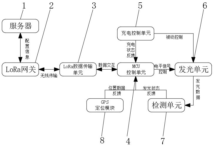
The invention discloses a LoRa-based intelligent spike light control system and an implementation method. The LoRa-based intelligent spike light control system comprises a server, a LoRa gateway, a LoRa data transmission unit, an MCU control unit, a charging control unit, a light emitting unit and a feedback unit, wherein the LoRa data transmission unit is used for performing low-power-consumptionlong-distance data transmission with the LoRa gateway through a LoRa wireless technology. According to the invention, wireless information transmission based on LoRa is supported, a wireless transmission function between a spike and a server is realized under the design of low power consumption, the working states of spikes on a plurality of roads can be planarly configured through instructions of the server, people are guided to drive in the correct direction in a severe environment, overspeed and traffic accidents are prevented, whether the spike works normally can be monitored in the control process, the position of the faulted spike can be fed back in real time, people can maintain the spike conveniently, and a better use prospect is brought.

Description

technical field [0001] The invention relates to the field of road stud light control, in particular to a LoRa-based intelligent road stud light control system and an implementation method. Background technique [0002] At present, road studs are widely used in domestic high-grade highways and municipal roads. At this stage, road studs are controlled by a simple solar circuit without a control unit. The luminous state of the road studs can only be changed by detecting the external brightness. Under this scheme, road studs The function of the spikes is single, and failures cannot be detected in time, and some spikes may not light up at the same time due to the sensitivity of components. In special circumstances, such as road construction enclosures and low visibility during the day, the working status of the spikes cannot be adjusted as required, resulting in waste of resources and prone to accidents; [0003] At present, the traditional road studs have a single function, and...

Claims


Application Information

Patent Timeline
Patent Type & Authority Applications(China)
IPC IPC(8): H05B47/105H05B47/19H02J7/00H02J7/35
CPCH02J7/0047H02J7/35H05B47/105H05B47/19Y02B20/40
Inventor 梁志平朱超成晟
Owner 江苏广宇科技产业发展有限公司
Why Eureka
Try Eureka